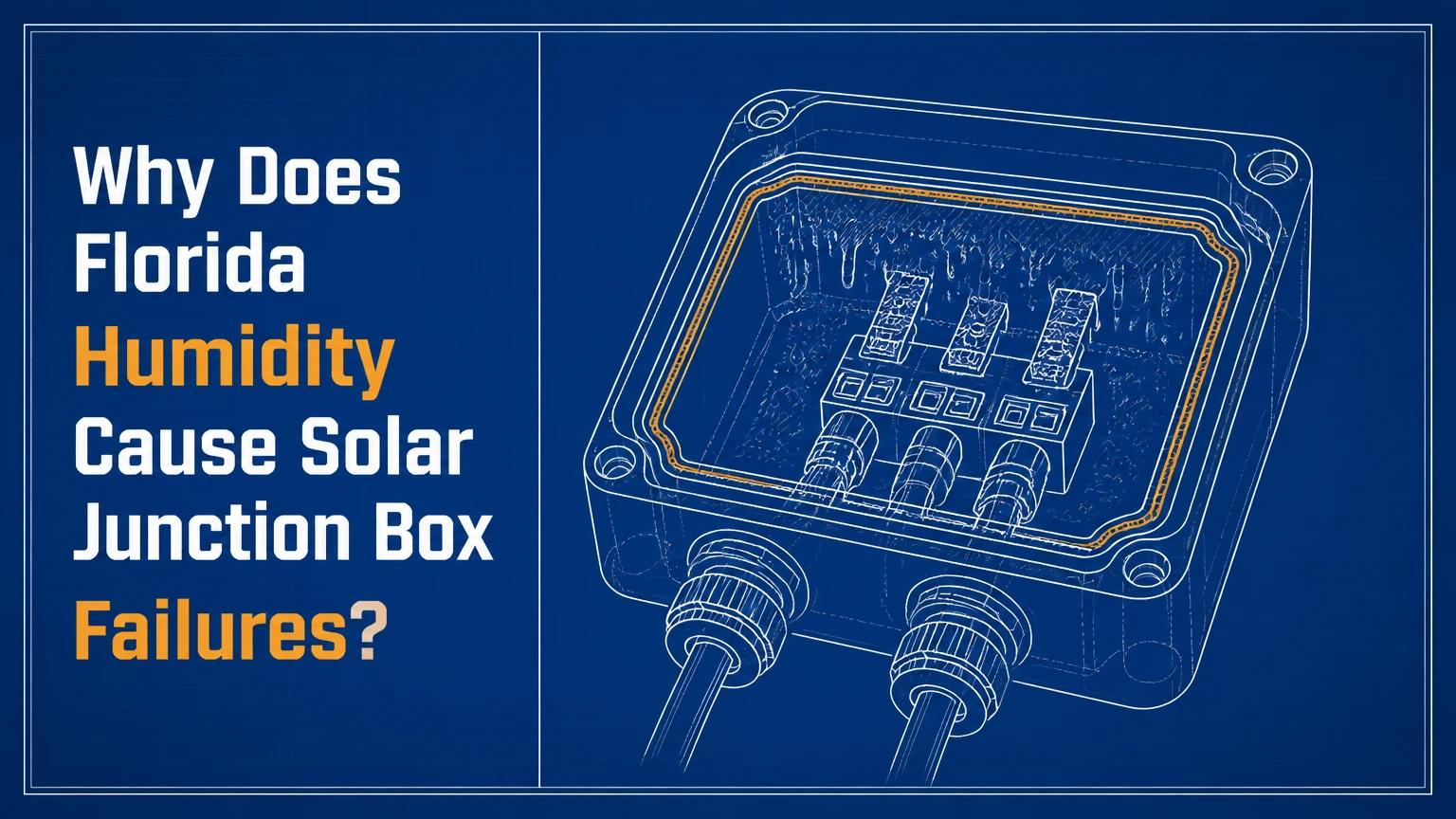
Florida humidity causes solar junction box failures when moist air reaches the box during repeated heating and cooling, then condenses on electrical parts or enters damaged seals. Heat, ultraviolet exposure, salt aerosol, and high-voltage direct current accelerate corrosion, leakage current, contact resistance, bypass-diode damage, and sometimes arcing.
Key Facts at a Glance
- A solar junction box connects the PV laminate’s bus ribbons to external DC cables and houses bypass diodes.
- Condensation occurs when a junction-box surface falls below the surrounding air’s dew point, not merely because relative humidity is high.
- A gasketed box can draw humid air through microscopic seal paths during daily temperature and pressure cycles.
- IP67 or IP68 describes a specified ingress test result; neither rating guarantees lifetime performance after UV, heat, installation, or material aging.
- A green or white deposit can indicate corrosion, but an inverter isolation fault can also originate in connectors, cables, backsheets, or racking.
- A technician should de-energize and isolate the PV circuit before opening a box or testing a module.
What Is a Solar Junction Box?
A solar junction box is the rear-mounted electrical enclosure that collects current from a photovoltaic module and transfers it to the string wiring. The enclosure typically contains busbar or ribbon terminals, bypass diodes, cable terminations, and a gasket, adhesive seal, or potting compound.
The junction box is not the same as an AC combiner box. A module junction box operates at the module’s DC voltage and current, while a combiner box joins multiple PV strings and may contain fuses, surge protection, and monitoring equipment. Confusing the two leads to incorrect inspection and replacement decisions.
| Component | Typical material or rating | Electrical function | Humidity-related risk |
|---|---|---|---|
| Enclosure base | UV-stabilized polycarbonate or PPE | Supports terminals and diodes | Cracking, warping, UV embrittlement |
| Lid and gasket | Silicone, EPDM, or molded polymer | Limits water and vapor entry | Compression loss, cuts, misplaced gasket |
| Busbar terminals | Tinned copper, copper, or brass | Transfers laminate current | Oxidation, fretting, resistance heating |
| Bypass diodes | Axial or surface-mount semiconductor | Routes current around shaded cell groups | Leakage, short circuit, thermal damage |
| Cable glands | Polymer and elastomer seal | Seals outgoing conductors | Wrong diameter, excess torque, looseness |
| Potting compound | Silicone, epoxy, or other resin | Encapsulates internal parts | Voids, poor adhesion, thermal stress |
A bypass diode normally protects a cell substring during shading. A defective diode can short one substring, reduce module voltage, or develop abnormal leakage. The diode does not make the junction box waterproof by itself.
How Does Barometric Breathing Create Condensation?
Barometric breathing occurs when a junction box expels air while heating and draws air back while cooling. Florida’s warm, moisture-laden air can enter through a weak gasket, cable seal, adhesive boundary, or microscopic housing crack; condensation follows when the internal surface temperature reaches the dew point.
The ideal gas relationship, PV = nRT, explains the direction of the pressure change, but it does not calculate the actual moisture ingress rate without seal geometry and leakage data. A sun-heated module can make the box interior substantially warmer than ambient, especially when bypass diodes dissipate power. A fast shower then cools the module surface and enclosure.
Consider air at 90°F and 75% relative humidity. Its dew point is approximately 81°F. If humid air enters a box and a metal terminal or polymer surface cools below 81°F, water can condense even though the box never fills with rainwater. Florida’s coastal air can also carry chloride-containing aerosol, which makes a thin moisture film more electrically and chemically aggressive.
| Event | Typical field condition | Junction-box effect | Likely consequence |
|---|---|---|---|
| Midday heating | Module back surface 140-185°F | Internal air expands; seal pressure changes | Air exits through weak paths |
| Thunderstorm arrival | Surface cooling over minutes | Internal air contracts | Moist ambient air is drawn inward |
| Nighttime cooling | Enclosure approaches outdoor temperature | Surfaces may reach dew point | Condensed film forms on terminals |
| Repeated wet-dry cycles | Daily or storm-driven | Deposits concentrate as water evaporates | Corrosion and leakage increase |
| Diode loading | Shading or mismatch raises diode heat | Local hot spot inside box | Seal and solder stress accelerate |
The sequence is not guaranteed in every box. A fully bonded, well-designed enclosure may exchange little air, while a nominally sealed box with a damaged cable entry can breathe repeatedly.
Why Do Heat, UV, and Salt Make Humidity More Destructive?
Florida heat accelerates chemical reactions and softens or ages some sealing materials, while UV radiation embrittles exposed polymers. Salt aerosol does not need visible seawater to matter: chloride deposits near coastal arrays can dissolve into a conductive film whenever humidity rises.
The National Renewable Energy Laboratory’s 2018 report Best Practices in Photovoltaic System Operations and Maintenance identifies moisture ingress, corrosion, connector problems, and thermal anomalies as important inspection concerns, but it does not assign one universal Florida junction-box lifespan. Field life depends on module design, installation workmanship, climate exposure, and loading.
IEC 61215 qualification includes damp-heat testing at 85°C and 85% relative humidity for a defined duration. That test is a qualification condition, not a promise that a field module will last a particular number of years in Florida. A module passing the test can still fail because of a damaged seal, manufacturing void, incompatible connector, or installation defect.
What Happens Inside the Electrical Connection?
Moisture creates a conductive path and supports electrochemical corrosion. Corrosion can reduce the effective contact area of a terminal, increasing resistance; the resulting heating follows P = I²R, so a small resistance increase becomes more consequential at high current.
Humidity-related electrical failures generally fall into four categories:
- Terminal corrosion: Oxidized or contaminated metal loses contact quality.
- Bypass-diode degradation: A diode can short, leak, or fail open after thermal and electrical stress.
- Insulation leakage: Moisture lowers resistance between energized conductors and grounded or nearby conductive parts.
- Arc or carbon tracking: High-voltage DC can sustain an arc across a contaminated or damaged path.
The chemical product is not always copper carbonate, despite a common simplified explanation. Copper corrosion products can include oxides, hydroxides, chlorides, sulfates, and carbonates, depending on contaminants, oxygen, moisture, and temperature. Green residue identifies corrosion or contamination, but laboratory chemistry is required to identify the exact compound.
Which Junction-Box Design Handles Florida Exposure Best?
A factory-potted junction box usually offers the strongest moisture barrier because potting removes most free internal air volume. A high-quality gasketed design can also perform well, but its result depends more heavily on gasket compression, lid geometry, adhesive bonding, cable entry design, and assembly quality.
| Design | Internal access | Typical ingress claim | Repair consequence | Florida suitability |
|---|---|---|---|---|
| Gasketed lid | Accessible diodes and terminals | IP65-IP67, model-specific | Sometimes repairable | Acceptable with verified design and inspections |
| Partially potted | Limited access | IP67-IP68, model-specific | Selective repair possible | Better moisture tolerance, harder service |
| Fully potted | No practical access | Often IP68, model-specific | Usually module replacement | Strong barrier, warranty-dependent |
| MLPE enclosure | Electronics vary by product | Product-specific IP rating | Manufacturer service often required | Depends on thermal and sealing design |
What Do IP67 and IP68 Actually Prove?
IP67 generally addresses dust protection and temporary immersion to the manufacturer’s specified test depth and time. IP68 indicates a manufacturer-defined continuous-immersion condition, so the test details matter. Neither rating proves resistance to decades of UV exposure, repeated thermal cycling, cable strain, salt contamination, or a cracked housing.
A potted box is not automatically superior in every respect. Potting can improve moisture resistance but can make diode replacement impossible, complicate thermal repair, and transfer mechanical stress if the compound and components expand differently. Gasketed boxes are easier to inspect, but opening them in the field creates a new sealing risk.
What Failures Does Florida Humidity Cause?
Florida humidity can produce visible corrosion, insulation faults, bypass-diode failures, connector heating, and intermittent power loss. The first symptom may appear at the inverter rather than at the module because the inverter detects the electrical consequence after moisture has already altered the circuit.
| Failure mode | Physical trigger | Electrical symptom | Typical field evidence |
|---|---|---|---|
| Terminal corrosion | Condensed moisture and salts | Reduced current, hot connection | Green, white, or dark residue |
| Shorted bypass diode | Moisture, heat, or surge stress | Module voltage drops by one substring | Lower voltage under isolation |
| Open bypass diode | Thermal or solder failure | Hot spot during shading | Thermal anomaly under shade |
| Insulation leakage | Wet contamination or damaged seal | Isolation or ground fault | Inverter fault after rain |
| Arc damage | High-voltage gap and carbonized path | Repeated trips, soot, fire risk | Pitting, melted polymer, odor |
| Cable-entry failure | Incorrect gland, strain, or connector | Intermittent string operation | Water tracks near cable exit |
A diode failure does not always reduce voltage by exactly one-third or two-thirds. Modules use different substring layouts, diode counts, electrical architectures, and measurement conditions. A voltage near one-third or two-thirds of expected open-circuit voltage can support a diode diagnosis, but it must be compared with the module design and tested safely.
How Can You Tell Whether Humidity Caused the Failure?
Humidity is a likely cause when an isolation fault follows rain, corrosion appears near a seal, and thermal or insulation testing identifies the affected module. A single inverter fault code cannot prove that the junction box is responsible because wet connectors, cable insulation, backsheets, optimizer housings, and racking can create similar symptoms.
Safe Troubleshooting Sequence
- Record the conditions. Note inverter codes, rainfall timing, array production, affected string, module serial numbers, and whether the fault clears after drying.
- Inspect without opening energized equipment. Look for cracked housings, lifted lids, melted polymer, soot, cable-entry distortion, residue, and cable exits facing upward.
- Compare string behavior. Use the monitoring portal or inverter data to identify a string or module with abnormal voltage and current.
- Use thermal imaging under suitable load. A qualified technician can scan during stable sunlight, preferably when the array is producing enough current to reveal resistance heating.
- Test insulation and conductors. A trained PV technician can isolate circuits and use an appropriate insulation-resistance tester according to equipment and module limits.
- Confirm the module architecture. Check the manufacturer’s wiring diagram before interpreting diode count or expected voltage.
- Document and escalate. Photograph evidence and contact the module manufacturer before cutting, opening, or repotting a warranty component.
Thermal imaging is useful but not definitive. A hot junction box can indicate resistance heating, a bypass diode under load, a poor connector, or shading-related behavior. A cool box can still contain moisture when the fault is intermittent or the array current is low.
| Test or observation | What it can indicate | What it cannot prove | Appropriate response |
|---|---|---|---|
| Isolation fault after rain | Moisture-dependent leakage | Junction box as the source | Sectionalize the DC circuit |
| Hot box under load | Resistance or diode heating | Exact failed component | De-energize and inspect |
| Reduced module Voc | Diode short or wiring issue | Exact diode count | Compare with module schematic |
| Green residue | Copper alloy corrosion | Specific chemical compound | Photograph and assess warranty |
| Fault disappears when dry | Moisture-sensitive insulation | Permanent safety | Treat as unresolved until repaired |
| Cracked lid or gland | Direct ingress pathway | Internal damage extent | Replace affected component or module |
High-voltage PV DC remains hazardous in daylight. Homeowners should not disconnect MC4-type connectors, open junction boxes, or measure live strings with an unsuitable meter.
How Much Does Junction-Box Repair or Replacement Cost?
A small connector or cable repair may cost approximately $150-$400 in total, while a module-level junction-box repair or replacement commonly reaches $250-$600 when diagnosis, roof access, testing, and documentation are included. A failed module can cost more than the box because labor, matching, disposal, and permitting may dominate the material price.
These are typical U.S. field ranges, not fixed Florida tariffs. Rooftop access, emergency service, array size, warranty coverage, and whether the backsheet is damaged change the final invoice.
| Work item | Typical material cost | Typical labor or service time | Decision note |
|---|---|---|---|
| Diagnostic visit | $0-$150 parts | 1-2 hours | Often credited toward repair |
| MC4-compatible connector repair | $10-$40 | 30-90 minutes | Requires exact connector compatibility |
| Junction-box kit | $20-$75 | 1-3 hours | Only if manufacturer permits repair |
| Module replacement | $150-$500 module | 1-3 hours | Add roof access and electrical testing |
| Commercial string investigation | $100-$300 per test point | 2-8 hours | Drone inspection may add cost |
| Warranty claim | Usually $0 parts | 1-6 weeks typical process | Preserve serial numbers and evidence |
A junction-box kit is not a universal replacement part. The replacement must match the module laminate, ribbon layout, diode specifications, current rating, voltage rating, adhesive system, and manufacturer repair instructions. Field-applied silicone can trap moisture, fail to bond to the backsheet, or release acetic acid during cure if the wrong chemistry is used near metals.
Should You Repair the Box or Replace the Module?
Replace the module when moisture reached the laminate, the backsheet is delaminated or punctured, the box is fully potted, arc damage is visible, or the manufacturer prohibits field repair. Repair can be reasonable when a serviceable gasketed box has a documented external seal failure, the laminate remains intact, and a qualified technician can restore the original electrical and environmental specifications.
| Condition | Repair suitability | Replacement priority | Required evidence |
|---|---|---|---|
| Damaged external connector only | High | Low | Connector and crimp inspection |
| Replaceable gasket with clean interior | Moderate to high | Low to moderate | Manufacturer procedure and insulation test |
| Corroded bus ribbon or terminal | Low | High | Resistance, thermal, and visual evidence |
| Fully potted box with failed diode | None in most cases | High | Product service policy |
| Burned housing or arc track | Low | Immediate | Thermal and fire-safety assessment |
| Wet or delaminated backsheet | None | Immediate | Visual inspection and electrical test |
An honest limitation matters here: a dry, visually clean junction box is not proof of reliability. Corrosion can remain beneath a terminal, and a fault can disappear after several dry days. Conversely, a one-time inverter isolation warning may originate outside the module and does not justify replacing an entire array without sectional testing.
Which Installation Practices Reduce Florida Failures?
Correct orientation, compatible connectors, controlled cable strain, and documented sealing are the most effective installation controls. Installers should keep cable exits downward or follow the module manufacturer’s approved orientation, avoid low points where water pools, and never mix visually similar but uncertified connector systems.
Florida Prevention Checklist
- Specify modules with a documented junction-box IP rating, diode arrangement, and warranty repair policy.
- Confirm that the module’s connectors and field connectors are listed as compatible by the connector manufacturers.
- Route cables so water cannot run along the cable into a gland or connector.
- Avoid overtightening cable glands, which can crack polymer housings or deform seals.
- Keep junction boxes clear of roof contact, standing water, and sharp racking edges.
- Record module serial numbers and junction-box photographs during commissioning.
- Review monitoring data after heavy storms and compare string current, voltage, and fault history.
- Inspect coastal arrays more frequently when salt deposits, corrosion, or wind-driven spray are visible.
- Use only manufacturer-approved sealants and replacement parts.
- Treat repeated isolation faults as a safety issue, not a nuisance alarm.
For coastal Florida, exposure distance alone is a poor decision rule. Wind direction, elevation, vegetation, salt spray, cleaning practices, and the presence of visible deposits can matter more than a simple “within five miles” threshold.
What Is a Realistic Florida Service Life?
There is no defensible universal Florida lifespan for gasketed or potted junction boxes. A well-made module may operate for 20-30 years, while an early seal, diode, connector, or backsheet defect can cause failure within a few years; manufacturer warranty terms and failure records are more useful than generic claims of five to eight years or 20 to 25 years.
| Equipment or condition | Typical planning range | Main uncertainty | Better planning method |
|---|---|---|---|
| New rooftop module warranty | 10-25 years | Product and manufacturer terms | Read product warranty |
| PV module design life | 25-30 years | Degradation and climate | Review warranty and test data |
| First visual inspection | 6-12 months after commissioning | Installation quality | Establish baseline images |
| Routine residential inspection | Every 1-2 years | Roof and coastal exposure | Increase after storms |
| Commercial thermographic survey | 1-2 times yearly | Array size and risk | Use repeatable weather conditions |
| Seal or diode failure | Any time during service | Design and workmanship | Trend monitoring and evidence |
A potted enclosure may reduce one moisture pathway, but it cannot prevent failure from a cracked cable, poor connector, thermal overload, laminate defect, or manufacturing contamination. The enclosure is one part of the module’s reliability chain.
How Should Homeowners, Installers, and O&M Teams Respond?
Homeowners should preserve fault records and arrange qualified testing rather than opening the box. Installers should isolate the source, document the defect, and evaluate warranty coverage. O&M teams should trend thermal, electrical, and visual evidence across the array instead of replacing modules solely from an inverter code.
Two practitioner rules prevent many wrong diagnoses:
- A rain-linked fault is a timing clue, not a component diagnosis. Sectionalize the array before naming the failed part.
- A warm junction box is a symptom with several causes. Compare it with neighboring modules under the same irradiance and electrical load.
- A replacement seal is not a complete repair unless the internal insulation test passes. Water may have already damaged terminals or potting boundaries.
For a commercial array, combine inverter event logs, string current comparisons, insulation testing, and repeatable infrared scans. For a residential array, a qualified technician can usually narrow the fault during one visit if the installer supplies the module wiring diagram and the inverter retains event history.
FAQ
Can Florida rain enter a sealed solar junction box?
Yes, rain can enter when a lid gasket is misaligned, a cable gland is damaged, a housing is cracked, or water follows a cable into the enclosure. Direct rain entry is only one pathway. Humid air can also enter during pressure cycling and later condense internally without visible leaks.
Does high humidity alone destroy a bypass diode?
High humidity alone usually does not explain immediate diode failure. Moisture must reach vulnerable materials, and electrical load, heat, contamination, surge stress, or manufacturing defects can accelerate the damage. A bypass diode that fails after wet weather should be tested against the module’s schematic and operating history.
Are solar panels near the Florida coast more vulnerable?
Coastal arrays generally face greater corrosion risk because salt aerosol can deposit conductive chlorides on exposed surfaces and connectors. Distance from shore does not provide a universal cutoff. Wind, elevation, spray direction, cleaning, enclosure design, and observed deposits determine the practical exposure.
Can I seal a leaking junction box with silicone?
Do not apply household silicone as a field patch. The product may not bond to the backsheet, may trap moisture, may release corrosive compounds during curing, or may violate the module warranty. Use an approved repair procedure, replacement component, or module replacement determined by a qualified PV technician.
Does an isolation fault always mean a wet junction box?
No. An isolation fault can originate in a junction box, DC connector, cable, optimizer, inverter, backsheet, racking component, or array wiring. Rain timing increases suspicion of moisture, but sectional insulation testing is needed to locate the fault before repair.
How can I reduce junction-box risk before buying panels?
Ask for the module datasheet, junction-box model, IP rating, diode arrangement, connector manufacturer, warranty terms, and approved field-repair procedure. Favor products with documented environmental testing and a service policy that explains whether a failed box is repairable or requires module replacement.
The Bottom Line
Florida humidity causes solar junction box failures through a chain of moisture ingress, dew-point condensation, contamination, corrosion, insulation leakage, and heat. Florida’s heat, UV exposure, thunderstorms, and coastal salt can shorten the time between seal degradation and electrical failure, but no universal five-year or 25-year lifespan applies.
The correct response is evidence-based: record weather-linked inverter faults, inspect safely, compare module behavior, use thermal and insulation testing, and verify the module design before interpreting voltage. Factory potting can reduce internal moisture risk, while careful cable routing, connector compatibility, inspection, and warranty documentation prevent many avoidable failures.