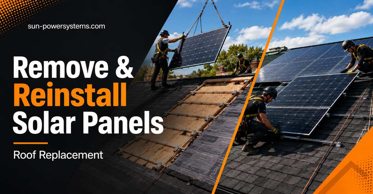
How to remove and reinstall solar panels for roof replacement is a 13-step “detach and reset” (D&R): plan and permit, power down, strip panels and racking, stage the hardware, then reset new flashing and remount after roofing. Expect 2–4 weeks of calendar time, 10–20 hours of on-site labor, and licensed-professional difficulty. Watertight new flashing on the new roof is the single factor that most determines success.
This is not a reverse installation. You are isolating up to 600 V of direct current, preserving a complex electrical map, and re-waterproofing a brand-new roof. The steps below are the exact sequence a competent crew follows written so a homeowner can understand, verify, and coordinate every stage, and so the licensed installer doing the physical work has a complete checklist.
⚠️ Safety-critical: A solar array cannot be “switched off” the way an appliance can. As long as the sun is up, the panels generate DC voltage. The disconnection, wiring, and remounting steps must be performed by a licensed solar electrician. This guide is a process reference and coordination tool, not a license to do 600 V DC work yourself.
Before You Start
Time required: 2–4 weeks total (permits, scheduling, weather). On-site labor: 4–8 hours to remove, 6–12 hours to reinstall.
Difficulty: Professional. The planning, permitting, and insurance coordination are yours; the electrical and rooftop work is a licensed installer’s.
Typical cost: $3,050–$11,450 depending on array size and roof type. Base D&R labor runs $150–$350 per panel. (Full breakdown near the end.)
Tools and materials the crew will use:
- Digital multimeter (e.g., Fluke) : to verify 0 V
- Insulation resistance tester / Megger : for fault-finding on reinstall
- Impact driver + torque wrench set to manufacturer spec (mid-clamp bolts typically 10–16 ft-lb)
- Deep-scan stud/rafter finder : locates rafters through new shingles
- New flashed mounts (e.g., IronRidge FlashFoot2, QuickMount QBase) : one per foot, never reused
- Lag bolts: 5/16″ diameter × 3½” length (into rafter), 3/16″–7/32″ pilot holes
- UV-stabilized roofing/solar sealant (e.g., Sikaflex, Geocel) for every penetration
- Watertight MC4 dust caps one per open connector
- Wooden pallets + foam or heavy cardboard interleaving for panel storage
- Outdoor-rated wire management clips (UV-resistant zip ties or cable clips)
Prerequisites and conditions:
- A licensed solar installer (ideally your original installer see warranty note below).
- Your original permit set, as-built drawings, and string/wiring diagram. If you don’t have them, request them from the installer or the permitting office before work starts.
- A confirmed roofing schedule so the roof is open for the shortest possible window.
- A dry-weather window. Never begin removal with rain forecast inside the roofing interval the exposed deck is the biggest risk in the whole job.
- Utility notification handled (see Step 1). This is the step almost every homeowner skips.
Phase 1: Plan, Permit, and Document the Array
Step 1: Pull permits and notify your utility
Confirm the permits and utility paperwork before anyone touches a bolt. Most jurisdictions treat a D&R as a system modification requiring an electrical/building permit; many utilities require written notice and a re-approval (permission to operate, or PTO) before the array can legally reconnect.
Call your utility and ask two questions: does reconnection require a new interconnection agreement, and will removing/reinstalling the system affect your net-metering rate? This matters enormously. In several states, a grandfathered net-metering rate can be lost when a system is “modified,” quietly cutting your export credit for the next 15–20 years.
You’ll know it worked when you hold a stamped permit (or written confirmation none is needed) and a utility email confirming your interconnection and net-metering status is preserved on reconnection.
Common mistake: Treating permits as a formality the contractor handles silently. Get the net-metering answer in writing most guides skip this, and the homeowner discovers the rate change on their first post-project bill.
Step 2: Run a baseline production test
Document that the system works before you remove it. Have the installer record the inverter’s live readings: per-string voltage and current, and total system output in kW, ideally against the manufacturer’s monitoring app (Enphase Enlighten, SolarEdge monitoring, etc.).
Screenshot the per-panel production so you have a “known good” reference. This is your evidence if a panel underperforms after reinstall you’ll know whether it was already weak or was damaged in the D&R.
You’ll know it worked when you have a dated production report showing each string or module producing within a few percent of the others under the same sun conditions.
Common mistake: Skipping the baseline, then having no way to prove a “dead” panel was fine beforehand which turns a warranty claim into a your-word-against-theirs argument.
Step 3: Photograph, map, and label every component
Create an engineering string map before disconnecting anything. Photograph the full array from multiple angles, then tag every panel, microinverter, and DC optimizer to its exact roof position on a layout drawing.
Go further than the summaries do: physically label each MC4 connector pair with numbered tape, note conduit and home-run routing, and record any clamp/torque or firmware settings. This 20-minute discipline is what prevents a two-hour reconnection nightmare in Step 12.
You’ll know it worked when any technician could rebuild the array from your photos and labels alone, without guessing where panel 14 goes.
Common mistake: Photographing the array “in general” but not labeling individual leads. Microinverter and optimizer systems fail to communicate if modules go back in the wrong sequence, and generic photos won’t save you.
Phase 2: Power Down and Verify Zero Voltage
Step 4: Shut down in the correct order : AC first, then DC
Power the system down from the grid inward. Turn off the AC disconnect switch, then the main solar breaker in the distribution panel, then isolate the DC side using the rapid-shutdown initiator or the string inverter’s DC disconnect.
The order matters and differs by system type. Microinverter arrays (Enphase) convert to AC on the roof and drop to a safe module-level voltage when AC is cut. String systems with optimizers (SolarEdge) use NEC 690.12 rapid shutdown to bring conductors to a safe voltage within 30 seconds. A pure string system without module-level electronics stays live at up to 600 V DC across the array until physically disconnected treat it as energized at all times.
You’ll know it worked when the inverter shows no output and its display/app confirms shutdown, and the rapid-shutdown indicator (if present) reads safe.
Common mistake: Assuming “the breaker is off” means the roof is safe. On a string system, the DC conductors between panels are still live in daylight regardless of any breaker.
Step 5: Confirm 0 V with a multimeter before touching metal
Verify voltage is actually zero don’t trust the switches. Using a digital multimeter, the technician measures across the open DC circuits and confirms each reads 0 V (or the expected safe rapid-shutdown value) before touching any rail, frame, or connector.
You’ll know it worked when the multimeter reads 0 V across every string measured, confirmed on at least two points, not one.
⚠️ This is the one verification you never skip or shorten. A single unverified live string is an arc-flash and electrocution hazard. If the reading isn’t zero (or the documented safe value), stop and find out why before proceeding.
Phase 3: Remove Panels and Racking
Step 6: Unclamp and lift each panel off the rails
Free the panels from the racking. Using an impact driver, back out the mid-clamps and end-clamps holding each module to the aluminum rails, then lift panels straight up and off. Two people per panel a residential module is ~40 lb and ~3.3 × 5.5 ft, and awkward in wind.
Keep hardware bagged and labeled by row; you’ll want the original clamps and bolts for reference even though flashing gets replaced.
You’ll know it worked when each panel lifts free with the connectors still attached (you disconnect them in the next step, on the ground or a stable surface not while balancing on the roof).
Common mistake: Prying or twisting a stuck panel. Torqued glass flexes and micro-cracks invisibly; the panel tests fine now and fails months later. Loosen the clamp fully instead of forcing the module.
Step 7: Disconnect the MC4 connectors and cap them
Separate the panels electrically. Release each MC4 locking connector using the proper MC4 unlocking tool (not pliers), working per your Step 3 labels so pairs are traceable.
Immediately seal every open MC4 connector with a watertight dust cap. Open connectors left exposed collect moisture and corrode the pins, which shows up later as resistance, heat, and ground faults.
You’ll know it worked when every module is disconnected, every open connector is capped, and each lead matches its label.
Common mistake: Leaving connectors uncapped “for a few days” during the roof work. Even light dew corrodes the pins; capping is 30 seconds of insurance against an expensive fault.
Step 8: Unbolt the rails, mounts, and ground wires
Strip the racking down to the roof. Detach the equipment grounding conductors, then unbolt the aluminum rails from the roof mounts and remove the old mounting feet entirely. On penetrative systems the old flashing stays embedded under the old shingles and is discarded with them.
You’ll know it worked when the roof is clear of all solar hardware and every old penetration is visible for the roofing crew to seal.
Common mistake: Leaving old mounting feet in place “to reuse.” Old flashing cannot be re-woven into a new shingle course — reusing it is the leading cause of post-project leaks (see troubleshooting).
Phase 4: Stage and Protect the Hardware
Step 9: Store panels upright, cushioned, and out of the sun
Stage the panels so they survive the interim intact. Stand modules vertically on edge on wooden pallets in a secure, enclosed, dry space (garage or box truck) never stacked flat, where weight and flex crack the cells. Insert foam or heavy cardboard between every glass face to prevent scratching and micro-cracking.
Keep panels out of direct sun while capped and idle, and don’t leave them staged longer than the roofing job needs. Store racking and hardware in labeled bins by row.
You’ll know it worked when panels are on edge, interleaved, capped, dry, and shaded, with nothing resting on the glass.
Common mistake: Laying panels in a flat stack on the driveway. It’s faster and it’s how cells crack the damage is invisible until production drops after reinstall.
Interim (1–3 days): The solar crew is off-site while the roofing team tears off the old roof and installs the new one. Confirm in advance who tarps the deck overnight and who owns liability if weather hits. This handoff, not the solar work, is where projects go wrong.
Phase 5: Reset Flashing and Racking on the New Roof
Step 10: Locate rafters and install new flashed mounts
Re-anchor into structure, not just decking. Using a deep-scan rafter finder, locate the structural rafters (typically 16″ or 24″ on center) through the new shingles and underlayment. Install brand-new, code-compliant flashed mounts over each rafter.
Drill a 3/16″–7/32″ pilot hole into the rafter center, drive a 5/16″ × 3½” lag bolt through the flashing and mount to manufacturer torque, and pack every penetration with UV-stabilized solar sealant. New flashing is woven into the new shingle courses so water sheds over, not under, it.
You’ll know it worked when every mount lands solidly in a rafter (not spongy decking), every flashing sits under the upslope shingle, and every lag hole is sealed.
Common mistake: Missing the rafter and lagging into decking alone. It holds in fair weather and pulls out under wind or snow load. If a pilot hole misses, seal it fully and re-drill into the actual rafter.
Step 11: Square and level the rails
Rebuild the racking to spec. Re-attach the aluminum rails to the new mounting feet, then check that runs are parallel and level along their length, within roughly 1/8″ over the array, so panels drain and shed debris properly. Respect the manufacturer’s maximum rail span between feet for your wind/snow zone.
You’ll know it worked when a level and string line confirm rails are straight, parallel, and pitched to drain no dips that pond water or sag panels.
Common mistake: Eyeballing the rails. Small racking errors compound across a 15-panel run, leaving the last modules cocked and stressed at the clamps.
Phase 6: Remount, Reconnect, and Recommission
Step 12: Remount panels per your string map
Rebuild the array in the exact original sequence. Mount the microinverters or optimizers back onto the rails first, matched to your Step 3 map, then lay panels row by row, reconnecting each MC4 pair to its labeled partner. Torque mid- and end-clamps to spec (commonly 10–16 ft-lb) and secure all cabling off the roof surface with outdoor-rated clips no wire touching shingles, where UV and abrasion destroy insulation.
You’ll know it worked when every panel is clamped, every connector is mated to its labeled pair, and no cable hangs against the roof.
Common mistake: Reconnecting modules in the wrong order on an optimizer/microinverter system. It causes communication and rapid-shutdown faults later; the string map exists precisely to prevent this.
Step 13: Power up and verify every panel produces
Recommission and confirm output matches your baseline. Re-energize DC first, then the main solar breaker, then the AC disconnect. Monitor the inverter or system app for 30–60 minutes and confirm every single module is reporting and producing.
Compare live per-panel output against the Step 2 baseline. A module reading low or offline flags a bad reconnection or a panel damaged in handling find it now, on the ground crew’s clock, not on your next utility bill.
You’ll know it worked when all modules report online, per-panel production matches the baseline within a few percent, and no fault codes appear after an hour of runtime. Then confirm the utility grants (or maintains) PTO.
Common mistake: Declaring victory when the total looks right. One dead panel hides easily in the array total verify at the per-module level.
Common Mistakes and How to Fix Them
Ground fault error after reinstall. A wire got pinched under a frame or rail and wore through. Use an insulation tester (Megger) to isolate the shorted string, then replace the damaged section and re-route it in UV-rated clips clear of pinch points.
Rapid shutdown or communication failure. Microinverters/optimizers went back in the wrong physical sequence. Map physical serial numbers to the monitoring software manually, or run the manufacturer’s rediscovery/rescan tool to rebuild the string mapping.
Post-reinstall roof leak. The crew reused old flashing or missed the rafter when lagging. Inject solar sealant into any missed pilot holes and replace compromised shingle sections with new flashed mounts driven into actual rafters — don’t patch over the symptom.
Panel underperforms versus baseline. Micro-cracking from flat stacking or from prying a stuck module. Compare against your Step 2 report; a module that’s dropped materially against its own former output likely cracked in handling and should go to warranty.
Lost net-metering rate on reconnection. The utility reclassified the “modified” system to a current, lower rate. Prevent it in Step 1 with written confirmation; if it’s already happened, appeal with your permit and proof the system capacity is unchanged.
Connector corrosion / heat at MC4. Connectors were left uncapped during the interim. Cut back the corroded ends and re-terminate with new MC4 connectors; don’t just re-mate corroded pins.
How the Process Changes: Variations
By mounting type. Penetrative asphalt or tile (high complexity): old flashing is discarded with the old roof and entirely new flashed mounts are woven into the new shingles the most leak-prone and most expensive variation. Standing-seam metal with clamps (low complexity): non-penetrative S-5!-style clamps grip the seams with set-screws, create zero holes, and are reused directly on the new metal roof with no new flashing. Ballasted flat roof (moderate but labor-heavy): no holes or flashing, but hundreds of concrete ballast blocks must be moved off and restacked by hand.
By inverter architecture. String-only systems stay energized at up to 600 V DC until physically disconnected highest shutdown risk. Microinverter (Enphase) and optimizer (SolarEdge) systems drop to safe module-level voltages at shutdown but demand exact per-module remapping in Step 12, so labeling discipline matters more.
By reason for the roof job. For an insurance-driven replacement (storm/hail), write the D&R labor ($150–$350/panel) as an explicit line item in the claim — insurers typically cover solar labor when the roof loss is covered. Have your contractor give the adjuster an itemized breakdown.
By system age. On an array over ~15 years old, price the D&R against replacement first. Paying labor-intensive D&R costs to put obsolete, degraded panels back on a new roof often makes less sense than scrapping (recycling) them and installing a new high-efficiency system while the roof is already open.
How Long It Takes and What It Costs
Total calendar window is 2–4 weeks, driven mostly by permits, utility approval, scheduling, and weather buffers not by the labor itself. Actual hands-on time is roughly 4–8 hours to remove and stage (Day 1), a 1–3 day roofing interim, and 6–12 hours to reset and recommission.
| Cost center | Cost per unit | 15-panel array | 25-panel array |
|---|---|---|---|
| Base D&R labor | $150–$350 / panel | $2,250–$5,250 | $3,750–$8,750 |
| New flashing | $15–$30 / mount | $300–$600 | $500–$1,000 |
| Engineering & permits | Flat fee (where required) | $200–$500 | $200–$500 |
| Unforeseen extras | Broken wires, critter damage | $300–$700 | $500–$1,200 |
| Total estimate | $3,050–$7,050 | $4,950–$11,450 |
You move toward the low end with a simple, accessible, single-story asphalt roof and reusable metal-clamp mounts; toward the high end with steep pitch, tile, multiple stories, long conduit runs, or discovered wiring/critter damage.
Frequently Asked Questions
Can I remove and reinstall the panels myself to save money? No. Solar strings run up to 600 V DC and cannot be de-energized while the sun shines. DIY risks arc flash, electrocution, invisible cell cracking, and a voided warranty. The planning, permitting, and insurance work is yours to own; the electrical and rooftop work belongs to a licensed installer.
Will a roof replacement void my solar warranty? It can, if the wrong party does the work. Workmanship and sometimes equipment warranties often require the original or a manufacturer-certified installer. Use your original installer where possible, and get written confirmation the warranty carries over on completion before you start.
Who should do the D&R : my roofer, my solar installer, or one bundled company? The original solar installer best preserves warranties and knows your layout; a third-party D&R specialist is often cheaper and faster but may void workmanship coverage; a bundled solar-roofing firm gives one contract and ends leak-liability finger-pointing, but may put roofers rather than certified electricians on your array.
What happens to my roof between removal and reinstall? It’s fully exposed during the 1–3 day interim, so the roofing crew must dry-in the deck and tarp overnight. Never schedule removal with rain in the forecast for that window the open deck, not the solar hardware, is the project’s biggest risk.
Do I have to tell my utility, and could it change my bill? Yes, in most areas. A D&R is usually a system modification requiring notice and reconnection approval (PTO). Critically, some utilities reclassify a “modified” system off a grandfathered net-metering rate confirm in writing that your rate and interconnection are preserved before work begins.
How do I know the reinstall was done right? Confirm three things: every panel reports online and matches your pre-removal baseline within a few percent after an hour of monitoring; no fault codes appear; and every roof penetration hits a rafter and is flashed and sealed. Then verify the utility has restored permission to operate.
Conclusion
Done in the right order, how to remove and reinstall solar panels for roof replacement comes down to disciplined documentation up front and watertight new flashing on the back end: map and label before you disconnect, verify 0 V before anyone touches metal, protect the panels on edge during the interim, anchor every new mount into a rafter, and recommission against your baseline until every module reports.
Handle the permits, utility net-metering confirmation, and insurance line items yourself, and leave the 600 V work to a licensed installer that division of labor is what gets a first-timer a leak-free roof and a fully producing array on the first attempt.