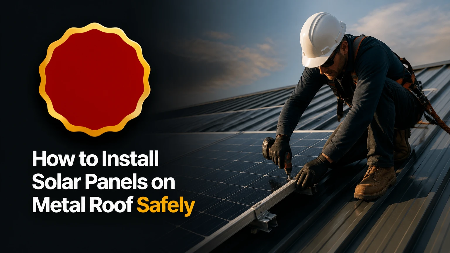
Installing solar panels on a metal roof requires a roof-specific racking system, structural attachment plan, electrical design, and local permit approval. Use non-penetrating clamps on compatible standing-seam roofs; use engineered brackets through the metal and into structural framing on corrugated or exposed-fastener roofs. A professional crew typically completes the physical work in 1-2 days, but design and permitting commonly take 3-8 weeks.
Key Facts at a Glance
- A standing-seam metal roof can accept solar panels without roof-sheet penetrations when the seam profile and clamp system are compatible.
- Corrugated and exposed-fastener roofs normally require brackets fastened through the sheet into rafters, purlins, or engineered blocking.
- A solar array adds commonly 2.5-4 pounds per square foot before local snow, wind, and seismic loads are calculated.
- Standing-seam clamps do not create an absolute zero-leak guarantee because incorrect clamp placement, damaged seams, and unrelated roof defects can still admit water.
- Solar modules commonly last 25-35 years, while a properly maintained standing-seam metal roof may last longer than the first array.
- Roof condition, structural framing, wind uplift, fire setbacks, electrical work, and manufacturer instructions determine whether an installation is acceptable.
Can Solar Panels Go on a Metal Roof?
Yes, solar panels can be installed on most sound metal roofs, but the attachment method must match the roof profile and supporting structure. Standing-seam roofs usually use seam clamps, while corrugated, trapezoidal, and exposed-fastener roofs use sealed structural brackets.
Metal roofing is often favorable for solar because it is durable, comparatively light, and compatible with several rack designs. The roof still needs an inspection before panel placement. Rust-through, loose fasteners, oil-canning that affects attachment, failed coatings, inadequate framing, or a roof near replacement age can make installation premature.
The National Renewable Energy Laboratory’s PVWatts tool uses location, array orientation, tilt, system losses, and weather data rather than a universal production number, so a 10 kW system will not produce the same electricity in Phoenix, Seattle, and Toronto. Roof material is only one design variable.
What must be verified before installation?
A qualified designer should verify:
- Roof profile, panel gauge, seam geometry, and manufacturer approval
- Rafter, truss, purlin, or structural-deck locations
- Roof age, corrosion, fastener condition, and coating compatibility
- Wind uplift, snow, seismic, and dead-load requirements
- Array setbacks required by the authority having jurisdiction
- Module dimensions, rail span, clamp zones, and service access
- Inverter location, conductor route, rapid-shutdown equipment, and grounding method
Which Mounting System Fits Your Metal Roof?
The correct mounting system depends on how the roof transfers loads, not merely on whether the roof looks ribbed or smooth. A standing-seam clamp grips a seam; a corrugated bracket transfers force through the sheet into framing; an adhesive laminate transfers force primarily through the roof surface and adhesive bond.
| Roof and mounting type | Attachment method | Typical added weight | Primary limitation |
|---|---|---|---|
| Standing seam with aluminum clamps | Seam clamp, rail, module clamp | 2.5-4 psf | Seam geometry must match clamp approval |
| Exposed fastener with structural bracket | Screw through rib into purlin or rafter | 2.5-4 psf | Every penetration needs a durable compression seal |
| Corrugated metal with rail-less bracket | Rib bracket and module clamps | 2.0-3.5 psf | Short rail spans increase attachment count |
| Thin-film laminate | Factory adhesive or approved bonding system | 0.5-1.5 psf | Lower efficiency and difficult roof replacement |
| Metal tile with tile-replacement mount | Flashing or replacement tile bracket | 3-5 psf | Tile shape and underlayment determine waterproofing |
Standing-seam clamps
Standing-seam clamps are usually the least invasive option because they do not pierce the roof sheet. Products such as S-5! clamps are approved by profile, load, and fastener configuration, not by brand name alone; the installer must select the model that matches the seam width, height, shape, and material.
A clamp’s set screw is not a substitute for engineering. Clamp spacing, rail span, edge distance, and uplift capacity must come from the racking manufacturer’s tables or a project engineer. Over-tightening can deform a seam or restrict thermal movement, while under-tightening can allow sliding under wind load.
Exposed-fastener and corrugated brackets
Penetrating brackets are normal for many agricultural and residential metal roofs. The bracket should sit on a rib or other approved attachment location, use a compatible EPDM sealing washer or manufacturer-approved gasket, and connect to framing capable of carrying withdrawal and shear forces.
A screw placed only in thin sheet metal may hold briefly but fail under cyclic wind loading. The installer must locate the purlin, rafter, or structural member and confirm screw embedment, diameter, corrosion resistance, and edge distance.
Thin-film and adhesive laminates
Thin-film laminates reduce roof loading and can produce a very low profile, but their lower efficiency can require more roof area for the same system capacity. Adhesive performance also depends on surface preparation, temperature, roof coating, moisture, ultraviolet exposure, and the product’s approved substrate.
Adhesive solar is not automatically the best high-wind solution. A low-profile surface can reduce aerodynamic disturbance, but the bond still requires tested wind-load data and installation at the manufacturer’s temperature and cleanliness limits. Removing bonded laminates can damage coatings and complicate reroofing.
How Do You Install Solar Panels on a Metal Roof?
A compliant installation follows seven controlled stages: assess the roof, design the array, prepare attachment points, install mounts and rails, secure modules, complete electrical connections, and test the system. The most important success factor is a verified load path from each attachment into the building structure.
Before You Start
| Planning item | Typical value | Required check |
|---|---|---|
| Professional roof installation | 1-2 workdays | Weather, roof access, crew safety plan |
| Design and permitting | 3-8 weeks | Utility, building, electrical, and fire approvals |
| Array dead load | 2.5-4 psf | Engineer adds snow, wind, and seismic loads |
| Typical residential module | 400-460 W, 19%-23% efficiency | Roof area, module dimensions, inverter voltage |
| Roof inspection | 1-3 hours | Corrosion, seams, fasteners, leaks, framing |
| Electrical commissioning | 2-6 hours | Voltage, polarity, insulation, grounding, monitoring |
Required materials include the approved clamp or bracket kit, rails or rail-less hardware, module end and mid-clamps, stainless or coated fasteners, UV-resistant cable clips, equipment-grounding components, conduit, labels, and inverter equipment. Do not substitute generic roofing screws, sealants, clamps, or grounding lugs without written compatibility approval.
Step 1: Inspect the Roof and Framing
Inspect the entire roof before carrying equipment upward. Mark corrosion, loose or missing fasteners, failed washers, open seams, damaged penetrations, ponding areas, coating failure, and locations where the underside framing cannot be reached or identified.
Use attic access, construction drawings, probing from safe locations, or approved structural drawings to map rafters and purlins. A typical residential array weighs 2.5-4 psf, but wind uplift and snow often govern the design rather than dead load.
You will know the inspection is complete when every planned attachment has a verified support path and the roof owner has a written repair decision.
Common mistake: installing over a roof that will need replacement in five years. Remove and reinstall solar later can add several thousand dollars in labor, disconnects, permits, and temporary storage.
Step 2: Design the Layout and Obtain Approval
Lay out modules around ridges, eaves, hips, valleys, roof penetrations, skylights, access paths, and required fire setbacks. Setbacks are jurisdiction-specific; a generic 3-foot rule is not universally correct, so the approved plan controls.
Confirm module clamp zones from the module manufacturer. Solar modules often require clamps within a defined distance from the short edges, and placing a clamp outside that zone can void the module warranty or reduce its tested load rating.
Design the electrical string voltage for the inverter’s cold-weather maximum. The National Electrical Code, local amendments, rapid-shutdown rules, conductor ratings, and rooftop fire access requirements must be applied by the responsible electrical designer.
You will know the layout is ready when the permit drawings show attachment locations, rail spans, conductor routes, equipment locations, and calculated design loads.
Common mistake: maximizing panel count before reserving access around roof edges and electrical equipment.
Step 3: Install Roof-Specific Mounts
Install standing-seam clamps only on the approved seam and at the manufacturer’s specified spacing. Clean the contact area, seat the clamp squarely, and torque the set screw with a calibrated wrench to the published value. Do not use a generic torque number because clamp values vary by product and seam material.
For corrugated or exposed-fastener roofs, mark the structural member, drill only the approved hole size, and drive the bracket fastener through the rib into the framing. Use the specified washer or gasket under the bracket and avoid placing attachments in drainage valleys unless the system is specifically engineered for that location.
The bracket must compress the seal without crushing it. Roofing sealant can supplement a tested gasket detail, but it cannot repair a misplaced screw or compensate for inadequate structural engagement.
You will know the mounts are correct when every clamp or bracket is aligned, torqued, documented, and supported by the approved attachment schedule.
Common mistake: fastening into sheet metal alone because the purlin location is inconvenient.
Step 4: Attach Rails and Manage Thermal Movement
Attach rails to the installed clamps or brackets with the specified hardware, splice locations, cantilever limits, and expansion provisions. Keep rail ends within the manufacturer’s maximum overhang and prevent rails from bearing against roof sheets.
Metal roofs expand and contract with temperature. Use approved rail splices, gaps, sliding interfaces, or separate rail sections where the racking design requires them; do not create a long rigid rail run that transfers thermal movement into seams or brackets.
Install cable clips so conductors remain clear of sharp metal edges and do not rest on the roof. Maintain bend radius, connector orientation, and separation from abrasive surfaces.
You will know the rail system is ready when rails are straight, fasteners are torqued, expansion details remain free, and cables are supported without tension.
Common mistake: using ordinary plastic ties that become brittle under ultraviolet exposure.
Step 5: Place and Clamp the Modules
Move modules with two-person handling or approved lifting equipment. Keep module glass, frames, connectors, and backsheets away from sharp ribs, dropped hardware, and concentrated foot traffic.
Place each module within the permitted clamp zones. Install end clamps at array boundaries and mid-clamps between adjacent modules, then torque them to the racking manufacturer’s specification. Panel frames must be fully seated and not twisted by uneven rails.
You will know the array is mechanically complete when every module has the specified clamp count, no clamp overlaps an unapproved frame area, and module gaps match the layout drawing.
Common mistake: tightening one side of a module fully before the opposite side, which can twist the frame and create uneven loading.
Step 6: Connect DC Wiring and Inverter Equipment
Connect modules only with compatible, fully engaged connectors from approved connector families. Confirm polarity and string length before plugging strings into an inverter, optimizer, combiner, or rapid-shutdown device.
Route conductors beneath modules with UV-rated clips, keep connectors off the roof, and protect any transition through metal with an approved bushing or gland. Use listed conduit and fittings for exposed exterior runs, with watertight entries at equipment.
The inverter location should satisfy manufacturer clearances, ventilation, service access, conductor limits, and local disconnect requirements. Battery systems add fire, ventilation, separation, and emergency-response requirements that do not disappear because the array is roof-mounted.
You will know the DC work is ready when polarity, open-circuit voltage, insulation resistance, connector engagement, and labeling pass the commissioning checklist.
Common mistake: cutting and reterminating factory connectors without using the listed tools and procedures.
Step 7: Ground, Test, Inspect, and Commission
Bond exposed metal racking and module frames with listed bonding hardware, equipment-grounding conductors, and compatible lugs. The exact grounding method depends on the racking system, module construction, inverter design, and electrical code; a bare copper wire run casually across aluminum rails is not a universal solution.
Avoid direct contact between incompatible metals. Aluminum roof panels, galvanized steel, stainless steel, copper, and treated lumber can create corrosion or compatibility problems when moisture and electrolytes are present. Use listed hardware, coatings, isolation washers, and bonding components specified for the environment.
Complete continuity, polarity, voltage, insulation, grounding, rapid-shutdown, inverter, and monitoring tests. Photograph attachment points and retain torque records, module serial numbers, permits, warranties, and as-built conductor routes.
You will know commissioning is complete when the authority having jurisdiction and utility requirements are satisfied, the inverter reports normal operation, and the owner receives shutdown instructions.
Common mistake: treating the inverter’s normal startup as proof that grounding, fire access, and roof attachment are correct.
Which Option Is Best for Different Roofs?
Standing-seam clamps usually offer the best roof-preservation outcome, while structural rib brackets are the practical choice for corrugated and exposed-fastener sheets. Adhesive laminates suit weight-sensitive designs only when their output, service life, wind testing, and removal consequences fit the project.
| Decision factor | Standing-seam clamps | Structural rib brackets | Adhesive laminates | Metal-tile mounts |
|---|---|---|---|---|
| Roof penetrations | 0 sheet penetrations | Commonly 4-12 per module group | 0 fastener penetrations | 1 flashed location per mount |
| Typical module efficiency | 19%-23% | 19%-23% | 11%-19% | 19%-23% |
| Typical service access | Modules removable | Modules removable | Removal may damage coating | Tile replacement required |
| Best roof condition | Sound seam, 5-30 years remaining | Sound sheet, known purlins | Smooth approved coating | Intact tile and underlayment |
| Main risk | Clamp mismatch | Seal or framing failure | Adhesive failure, reroof difficulty | Flashing and tile breakage |
| Typical labor duration | 1-2 days | 1-3 days | 1-2 days | 2-4 days |
Is a standing-seam roof always the best choice?
A standing-seam roof is usually the strongest candidate when its seams match a tested clamp and the roof has adequate remaining life. Non-penetrating attachment reduces the number of roof-sheet holes, but it does not eliminate structural design, wind-uplift, corrosion, or workmanship requirements.
Standing-seam systems are not suitable when seams are too narrow, mechanically locked in a way the clamp does not approve, damaged, widely spaced beyond rail limits, or made from a material incompatible with the clamp. A seam clamp also cannot repair a roof leak that existed before the array.
Winner verdict: Choose standing-seam clamps when profile compatibility and structural capacity are documented.
When are penetrating brackets the better solution?
Penetrating brackets are better when the roof is corrugated, trapezoidal, exposed-fastener, or otherwise lacks a usable vertical seam. Proper brackets can provide a durable installation when screws engage structural framing and the gasket detail is installed under controlled compression.
The method requires more roof maintenance discipline. EPDM washers age, fasteners can loosen, and future roof coating or sheet replacement may require array removal. Coastal salt, ammonia from agricultural buildings, and industrial pollutants require corrosion-resistant hardware selected for the exposure category.
Winner verdict: Choose structural brackets when framing access and a tested sealing detail are available.
How Much Does Solar on a Metal Roof Cost?
A typical professionally installed 10 kW residential system may cost approximately $25,000-$35,000 before incentives, or $2.50-$3.50 per watt, with metal-roof complexity, electrical upgrades, location, and equipment accounting for much of the variation. Incentives, utility rules, roof repairs, and battery storage can change the final price substantially.
| Cost component for a 10 kW system | Typical range | Main price driver |
|---|---|---|
| PV modules | $7,000-$11,000 | 400-460 W module count and brand |
| Racking and roof attachment | $2,000-$5,500 | Clamp profile, penetrations, engineering |
| Inverter and electrical balance | $3,500-$8,000 | Microinverters, optimizer, service upgrade |
| Labor, design, and permits | $7,500-$12,000 | Region, roof pitch, access, inspection |
| Battery storage, optional | $9,000-$18,000 | 10-15 kWh usable capacity |
| Total before incentives | $25,000-$35,000 | System size and site conditions |
The federal Residential Clean Energy Credit has historically provided a 30% credit for eligible systems under qualifying rules, but tax law, project date, ownership structure, and eligibility can change. Verify current requirements with the Internal Revenue Service and a tax professional rather than treating a generic percentage as guaranteed.
A simple payback example illustrates sensitivity. If a 10 kW array produces 13,000-15,000 kWh per year and offsets electricity priced at $0.16 per kWh, annual bill displacement is approximately $2,080-$2,400 before export limitations, fixed utility charges, degradation, and maintenance.
| Variable | Low case | High case | Effect on payback |
|---|---|---|---|
| Installed price | $25,000 | $35,000 | Lower cost shortens payback |
| Annual generation | 13,000 kWh | 15,000 kWh | Higher production improves savings |
| Electricity value | $0.12/kWh | $0.24/kWh | Rate structure often dominates |
| Annual bill displacement | $1,560 | $3,600 | Export credit changes result |
| Simple pre-incentive payback | 6.9 years | 22.4 years | Not a universal forecast |
The table uses separate low and high assumptions, not a single typical project. Net metering caps, time-of-use rates, shading, snow, curtailment, and battery dispatch can make a spreadsheet estimate materially wrong.
What Problems Occur After Installation?
Most post-installation problems trace to roof attachment, conductor protection, incompatible materials, or inadequate commissioning rather than to the photovoltaic cells. The safe response is to de-energize only through the approved procedure and use a qualified roofer or electrician for work involving live DC circuits or roof penetrations.
| Symptom | Likely cause | Safe first response | Permanent correction |
|---|---|---|---|
| Water below a bracket | Loose screw, failed gasket, misplaced hole | Stop interior exposure and document location | Replace fastener or bracket using approved flashing detail |
| Morning popping noise | Thermal movement or constrained rail | Compare sound with temperature changes | Correct expansion or clamp installation |
| Ground-fault alarm | Chafed conductor or wet connector | Follow inverter shutdown procedure | Replace damaged cable and test insulation |
| Array slides on seam | Under-torqued or mismatched clamp | Keep people away from array edge | Replace and torque approved clamps |
| Brown roof staining | Galvanic or coating corrosion | Photograph and isolate contact | Replace incompatible hardware and damaged sheet |
| Low energy production | Shade, snow, clipping, failed optimizer | Compare monitoring data with weather | Repair equipment or revise shade assumptions |
How do you prevent leaks?
Prevent leaks by using a roof-specific attachment detail, locating structural members before drilling, installing approved gaskets under correct compression, and recording every penetration. Roofing cement smeared around a random screw is not equivalent to a tested bracket and flashing assembly.
Standing-seam systems reduce penetration-related risk but still require inspection for damaged seams, clamp mismatch, and trapped debris. Penetrating systems deserve a documented leak check after installation and again after the first major rain or snow event.
Do not inject silicone into a leaking hole as the final repair. The durable fix may require removing the fastener, inspecting the substrate, replacing the gasket or bracket, and repairing the sheet according to the roof manufacturer’s method.
How should thermal expansion be handled?
Thermal expansion is handled through approved rail splices, rail gaps, sliding attachments, and clamp placement that does not lock the roof seam against its normal movement. The correct detail comes from the racking and roof manufacturers, not from a universal gap dimension.
Metal panels can move more than the solar rail system over daily temperature changes. Rigidly joining long rail runs to multiple seams can transfer movement into fasteners, coatings, and roof sheets, producing noise or fatigue.
Should You Install Solar Yourself?
A capable homeowner may assemble some permitted low-voltage equipment, but roof-mounted solar is not a suitable first-time DIY project when it involves roof access, structural drilling, utility interconnection, high-voltage DC, or rapid-shutdown equipment. Electrical licensing, fall protection, permits, and inspection rules vary by jurisdiction.
DIY work is most defensible when the homeowner has documented roofing and electrical experience, the local authority permits owner-builder work, engineered attachment instructions are followed exactly, and a qualified electrician performs required tests and interconnection. Never walk directly on fragile or wet metal panels, and never disconnect energized PV connectors under load.
Hire a contractor when the roof is steep, the array is near an edge, framing is concealed, the building is agricultural or coastal, the service panel needs modification, or the roof has corrosion. A reputable proposal should identify the roof profile, attachment product, structural assumptions, wind and snow design values, electrical equipment, workmanship warranty, roof warranty coordination, and post-installation leak procedure.
What Should You Confirm Before Signing?
Use this document checklist before approving a solar contract:
- Roof inspection report with remaining service-life estimate
- Roof profile and attachment-product identification
- Structural calculations or approved load tables
- Module, inverter, racking, and grounding equipment model numbers
- Array layout showing access and fire setbacks
- Permit, inspection, utility, and rapid-shutdown responsibilities
- Roof warranty statement from the roofing manufacturer or installer
- Workmanship, leak, equipment, and performance warranty terms
- Cost before incentives, incentive assumptions, and payment schedule
- Removal and replacement price if the roof needs work later
The contract should distinguish equipment warranties from workmanship warranties. A 25-year module warranty does not mean the roof attachment, inverter, labor, or water intrusion has 25 years of coverage.
FAQ
Does a metal roof reduce solar panel efficiency?
Metal roofing does not inherently reduce photovoltaic efficiency. Array orientation, tilt, shading, module temperature, inverter losses, snow, and roof ventilation have greater effects; a ventilated rack can improve operating temperature compared with a roof-integrated surface, while a reflective roof may reduce heat absorption.
Can solar panels be installed over an old metal roof?
Solar panels should not cover a metal roof with active corrosion, failed seams, widespread loose fasteners, or insufficient remaining service life. If replacement is likely within the array’s first decade, reroofing first usually avoids the labor and permit cost of removing and reinstalling the solar system.
Do solar panels protect a metal roof?
Solar panels shade portions of a metal roof from sunlight and precipitation, but they do not repair corrosion or protect every exposed surface. Racking can also create debris traps and maintenance access issues, so the array should be inspected without assuming covered metal is maintenance-free.
Are solar panels on a metal roof noisy?
Solar panels can produce occasional clicking or popping when rails, seams, or brackets move with temperature. Persistent noise may indicate constrained expansion, loose hardware, or a damaged seam, especially when the sound began after installation and changes with morning warming.
How often should a solar array on a metal roof be inspected?
Inspect the array and roof at least annually, and after severe wind, hail, heavy snow, or unusual inverter alarms. Check exposed-fastener gaskets and corrosion-prone areas more closely in coastal or agricultural environments, while never walking on modules or unsupported metal sheets.
Can batteries be added to a metal-roof solar system later?
Batteries can usually be added later if the inverter, service equipment, communications system, and utility rules support expansion. A future battery may require a new inverter, backup-load panel, fire-clearance review, and electrical permit, so reserve wall space and conduit pathways during the initial design.
The Bottom Line
The safest way to install solar panels on a metal roof is to match the roof profile with an approved clamp or bracket, verify the structural load path, preserve thermal movement, protect every conductor, and complete the required electrical and roof inspections. The exact keyword question, how to install solar panels on metal roof, has no single universal hardware answer: standing seam, corrugated, exposed-fastener, and metal-tile roofs require different attachment details. Plan the roof condition, permits, wind and snow loads, electrical design, and future reroofing before comparing panel prices.