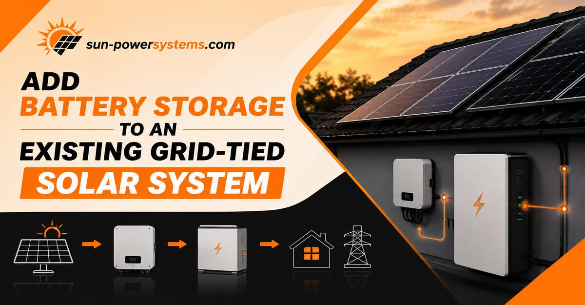
Adding battery storage to an existing grid-tied solar system upgrades your home into a self-sufficient energy hub that operates during grid outages. By completing these seven installation and commissioning steps, you will safely mount the storage hardware, isolate critical loads, and calibrate your energy management system. Success relies entirely on correctly matching your inverter-to-battery charging thresholds.
Before You Start
- Time Required: 2 to 6 weeks for engineering/permits; 1 to 2 days for physical installation.
- Difficulty Level: Advanced (Requires licensed electrician for panel work and utility interconnection).
- Cost Range: $5,500 – $8,500 (5–7 kWh backup); $10,500 – $16,000 (10–15 kWh whole-home); $18,000 – $34,000+ (16–30 kWh full independence).
- Tools & Materials:
- Lithium Iron Phosphate (LFP) Battery pack (e.g., 10 kWh to 15 kWh)
- Battery Inverter (for AC-coupled) or Hybrid Inverter (for DC-coupled)
- Backup Gateway / Automatic Transfer Switch
- Secondary Critical Loads Sub-panel (with assorted breakers)
- Current Transformer (CT) Sensors (2x)
- Torque wrench (calibrated to in-lbs)
- Digital Multimeter (Cat III or Cat IV rated)
- Conduit (EMT or PVC), 4 AWG to 2/0 AWG copper wiring
- Prerequisites: Approved utility interconnection agreement and local building permits.
Phase 1: Planning and Approvals
Step 1: Audit Your Current Inverter and Size the Battery
Calculate your solar array’s maximum AC output and select a battery capacity that complies with the continuous charge limits of your chosen retrofitting architecture.
If you are using an AC-coupled setup (keeping your existing inverter), check the data sheet of your target battery inverter for its maximum continuous charge rate. The AC output of your existing solar inverter must not exceed the battery’s maximum charge acceptance rate by more than 125% to 150% (depending on local codes and manufacturer limits). For example, if you have a 7.6 kW solar inverter, you need a battery system capable of absorbing at least 5 kW to 7.6 kW of continuous power to prevent the battery from tripping offline during peak afternoon generation. Choose a Lithium Iron Phosphate (LFP) battery to ensure a 95%–100% Depth of Discharge (DoD) and 6,000+ life cycles.
You’ll know it worked when: Your selected battery’s continuous kW charge rating aligns with your existing solar inverter’s peak kW output, ensuring no clipping or system overloads.
Common Mistake: Ignoring the “Inverter to Battery Ratio” rule. If a massive 10 kW solar array dumps full power into a battery inverter rated for only 5 kW during an off-grid event, the battery inverter will instantly shut down to protect itself from overcurrent.
Step 2: Draft the Single-Line Diagram and Pull Permits
Draft a formal single-line electrical schematic detailing the integration and submit it to your municipality and utility provider.
Hire a solar design engineer to generate a schematic showing the exact wire gauges, conduit sizes, breaker amperages, and the location of the backup gateway. Submit this schematic to your local building department for electrical permits. Simultaneously, submit an interconnection application to your utility company. You must detail whether the system will operate in a self-consumption mode or if it requires full islanding capabilities during grid outages.
You’ll know it worked when: You receive a stamped permit from your local building authority and a conditional pre-approval letter from your utility company allowing the installation to proceed.
Common Mistake: Beginning physical installation before utility pre-approval. Unapproved hardware modifications can result in hefty fines or immediate remote disconnection by the utility grid operator.
Phase 2: Physical Retrofitting
Step 3: Mount the Battery and Hardware Enclosures
Mechanically secure the battery enclosure, inverter, and backup gateway to structural studs while strictly observing required thermal clearances.
Locate a weather-protected exterior wall, garage, or utility room. Anchor the heavy LFP battery enclosure (often weighing 200–300 lbs) using heavy-duty lag bolts directly into wall studs, or utilize a manufacturer-engineered floor-mount stand. Maintain a minimum of 36 inches of working clearance in front of the battery and 12 to 18 inches of clearance on the sides and top to allow for passive heat dissipation. If doing an AC-coupled retrofit, mount the separate bidirectional battery inverter next to it. Torque all high-voltage DC terminal lugs inside the battery casing exactly to the manufacturer’s spec (typically 45–50 in-lbs) using a calibrated torque wrench.
You’ll know it worked when: The equipment is rigidly mounted, perfectly level, and all high-voltage DC connections pass a visual inspection and a “tug test” without any movement.
Common Mistake: Under-torquing the DC battery cables. Loose connections increase electrical resistance, causing extreme heat buildup that can melt terminals and trigger fatal BMS (Battery Management System) thermal faults.
Step 4: Split the Switchboard and Install the Backup Gateway
Install a backup isolation gateway and migrate your essential household circuits to a new critical loads sub-panel.
Turn off the main utility breaker. Install the backup gateway (Automatic Transfer Switch) between your utility meter and your main distribution panel. Next, mount a new critical loads sub-panel beside your main panel. Physically pull the hot wires for your refrigerator, internet router, well pump, and core lighting circuits out of the main panel and re-terminate them into new breakers within the sub-panel. Leave heavy, non-essential loads (like central AC, electric ovens, or EV chargers) in the main panel. Route the output of your battery inverter directly into the critical loads sub-panel.
You’ll know it worked when: A digital multimeter reads 0 Volts across all busbars during the dead-test, and the transferred circuits are securely seated in the new sub-panel.
Common Mistake: Assuming auto-backup is a standard feature. If you skip installing the dedicated backup gateway and sub-panel, your battery will simply turn off during a blackout, acting only as a daily energy shifter rather than a backup power supply.
Step 5: Clamp and Calibrate the Current Transformers (CT)
Snap the smart Current Transformer (CT) sensors around the incoming main service wires to monitor the directional flow of electricity.
Locate the two main thick incoming utility cables (Line 1 and Line 2) inside your main distribution panel, or directly inside the backup gateway. Snap one CT clamp securely around each wire. You must orient the clamps so the structural directional arrow printed on the plastic casing points directly toward the home’s electrical loads (away from the utility meter). Route the thin communication wires from the CT clamps back to the battery inverter’s communication port and secure them in the designated terminals.
You’ll know it worked when: The CT clamps lock shut with a click, the arrows point downstream toward the breakers, and the wires are clear of any high-voltage busbars.
Common Mistake: Installing the CT clamps backward. If the arrow points toward the grid, the battery software will think the home is exporting power when it is actually importing. The battery will fail to charge or discharge at the correct times.
Phase 3: Activation
Step 6: Flash Firmware and Perform the Grid-Isolation Test
Power on the system, push the latest firmware to the Battery Management System, and manually simulate a grid blackout.
Turn on the DC battery disconnects, followed by the AC breakers. Connect your laptop or smartphone to the inverter’s local commissioning Wi-Fi network. Follow the commissioning wizard to update the firmware and set your grid profile (which dictates voltage and frequency limits). Once the system is actively running and the battery is charging, perform a grid-isolation test: physically throw your main service breaker to the “OFF” position. The backup gateway should mechanically click, and your critical loads sub-panel should immediately switch to battery power within 10 to 20 milliseconds.
You’ll know it worked when: Your digital clocks and internet router remain powered on seamlessly the moment the main breaker is shut off, and the inverter app displays “Off-Grid Mode.”
Common Mistake: A frequency-shift power management conflict. If the system drops offline mid-day during a simulated blackout, the battery inverter is ramping up the micro-grid frequency (Hz) too aggressively. You must enter the solar inverter app interface and expand its ride-through frequency settings to conform with the battery’s off-grid parameters.
Step 7: Pass Municipal Inspection for Utility PTO
Schedule a local municipal electrical inspection to review the conduit, labeling, and grounding, followed by the final utility sign-off.
Apply all necessary safety placards, warning labels, and rapid-shutdown markers to your electrical panels, battery enclosure, and exterior conduit routes as required by the National Electrical Code (NEC). Walk the local municipal inspector through the installation to verify grounding paths and wire gauges. Once the municipal inspector signs the permit card, submit this finalized card to your utility company. Do not leave the system operating in grid-export mode until you receive the formal Permission to Operate (PTO) letter.
You’ll know it worked when: You possess a digitally or physically signed PTO document from your utility, allowing the battery to safely and legally interact with the wider electrical grid.
Common Mistake: Mixing component manufacturers without verifying firmware handshakes. A third-party battery often cannot communicate natively with an older string inverter; if the inspector notices a lack of closed-loop communication integration required by local utility tariffs, they will fail the inspection.
Common Mistakes and How to Fix Them
- Symptom: The home is importing expensive grid power even though the battery is at 90% capacity.
- Fix: This is almost always a miscalibrated or inverted CT clamp. Open the main distribution board and check the directional arrow printed on the plastic casing of the CT clamp. Unclip it and reverse it so the arrow points toward the home’s electrical loads.
- Symptom: The solar inverter shuts completely off when the grid goes down (while the battery is running).
- Fix: The solar inverter’s frequency-watt response is too narrow. When off-grid, the battery inverter shifts the frequency to curtail solar production. Hire an authorized technician to log into the solar inverter and widen the frequency ride-through thresholds so it gently throttles down instead of faulting out.
- Symptom: The battery drains rapidly overnight despite low household usage.
- Fix: Non-essential heavy loads were mistakenly left on the backup circuit. Review your critical loads sub-panel and verify that large appliances like electric water heaters, hot tubs, or EV chargers were not accidentally migrated over during Step 4.
System Variations by User Profile
The correct retrofitting approach depends heavily on your existing solar hardware and your primary financial goals:
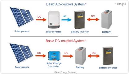
- The “Legacy Solar” Owner (DC-Coupled Swap): If your string inverter is 8–10 years old and nearing the end of its warranty, do not buy a separate AC-coupled battery inverter. Remove the aging string inverter entirely and install a new Hybrid Inverter. The DC electricity produced by the panels flows directly into the hybrid inverter and straight down into the battery without intermediate conversions, achieving 92%–96% round-trip efficiency.
- The “Modern Microinverter” Owner (AC-Coupled Add-on): If your system uses microinverters (like Enphase) mounted beneath the panels, AC coupling is your only practical pathway. The electricity coming down from the roof is already AC power. Add a bidirectional battery inverter and storage pack directly to your indoor switchboard with zero rooftop structural alterations. Expect 85%–89% round-trip efficiency due to the triple-conversion penalty.
- The “Time-of-Use Optimizer” (No Backup Needed): If you rarely experience grid outages but face high evening electricity rates (e.g., 4:00 PM to 9:00 PM), install a basic AC-coupled system without the isolation gateway or critical loads panel. The battery acts purely as an economic energy shifter, saving you roughly $2,000–$3,500 in physical hardware and labor costs, though it will not provide power during a blackout.
How Long Does It Take / What Does It Cost?
The true cost of adding battery storage relies heavily on hardware capacity and localized structural labor.
| System Goal | Battery Capacity | Hardware + Labor Cost | Typical Coverage |
| Entry-Level Backup | 5 – 7 kWh | $5,500 – $8,500 | Refrigerator, LEDs, Wi-Fi router overnight. |
| Standard Whole-Home | 10 – 15 kWh | $10,500 – $16,000 | Standard household items, microwave, low-draw appliances. |
| Full Independence | 16 – 30 kWh | $18,000 – $34,000+ | Central A/C, heavy pumps, EV charging during extended blackouts. |
- Engineering & Permitting: 2 to 6 weeks depending on municipal backlogs.
- Physical Installation: 1 to 2 full working days on-site.
- Inspection & Utility PTO: 1 to 4 weeks after physical installation is completed.
Frequently Asked Questions
Can I mix different battery chemistries in a retrofit?
No. You cannot safely wire a Lithium Iron Phosphate (LFP) battery bank in parallel with older Lithium Nickel Manganese Cobalt (NMC) or Lead-Acid batteries. The differing voltage curves and thermal profiles will cause extreme imbalances and immediate Battery Management System faults.
Do I have to notify my utility company if I don’t export battery power?
Yes. Even if you program the system for zero-export to the grid, you must sign an interconnection agreement. Unpermitted grid-tied battery systems pose a severe electrocution hazard to utility lineworkers attempting to repair downed power lines.
What happens to clipped solar energy in a retrofit?
If you utilize a DC-Coupled hybrid swap, the hybrid inverter can harvest excess “clipped” DC energy that exceeds your home’s immediate AC limits and dump it straight into the battery. In an AC-Coupled retrofit, that clipped energy remains permanently lost.
Why do Lead-Acid batteries degrade faster than LFP?
Lead-Acid (AGM/Gel) batteries degrade rapidly through sulfation if discharged past 50%–60% of their total capacity. Modern LFP units feature a 95%–100% Depth of Discharge (DoD), allowing you to use the entire stored capacity without damaging internal cell chemistry.