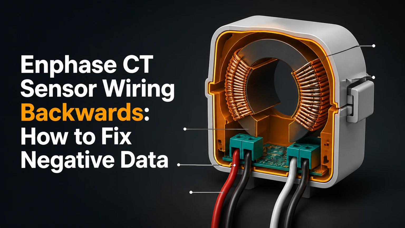
Enphase CT sensor wiring backwards usually means the consumption CT polarity is reversed, the CT is on the wrong conductor, or its current phase does not match the IQ Gateway voltage reference. Correct the issue through an available Installer Portal polarity setting or by having a qualified electrician correct CT orientation and phase wiring, then validate readings with solar production off and a known household load.
Key Facts at a Glance
- A reversed Enphase consumption CT commonly reports household import as negative power, especially when solar production is zero.
- CT arrow direction alone does not diagnose every fault; a swapped L1/L2 reference can produce similar symptoms.
- Consumption CTs must measure the intended service conductors and must not accidentally include a solar feeder and the utility conductors in the same measurement path.
- Homeowners should not open a service panel or touch service conductors, even when the main breaker is switched off.
- A typical installer diagnostic takes 15-30 minutes; a licensed electrician service call commonly costs about $150-$300 in North America.
- A small transient negative value can occur during battery discharge or telemetry changes, but sustained nighttime negative consumption is not normal.
What Does Negative Enphase Consumption Mean?
Negative Enphase consumption means the IQ Gateway calculates power flow in the opposite direction from the configured load direction. The most common cause is reversed CT polarity, but cross-phasing, incorrect conductor placement, a configuration error, or a damaged CT can create the same visible symptom.
An Enphase current transformer surrounds a single energized conductor and produces a secondary signal proportional to current. The IQ Gateway compares that current signal with a voltage reference for the relevant electrical phase. The resulting calculation determines whether the site is importing energy from the grid or exporting energy toward it.
The practical diagnosis depends on timing. If consumption is negative at night while the photovoltaic system produces zero watts, reversed polarity or phase mismatch is more likely than a solar-feed placement problem. If the graph becomes negative only when solar output rises, investigate CT location and meter configuration before changing polarity.
Enphase’s CT troubleshooting material summarizes the orientation rule as: “The arrow on the CT should point toward the load.” The exact installation arrangement still depends on the IQ Gateway model, service topology, and Enphase installation documentation for that system.
The electrical mechanism
Alternating current changes direction at the line frequency, usually 60 Hz in North America and 50 Hz in many other regions. A CT installed in the opposite direction reverses the current waveform relative to the Gateway’s voltage waveform, so imported load can be interpreted as exported power.
A phase mismatch is different. The CT may face the correct direction, yet its L1 current signal can be paired with the L2 voltage reference. The result is an incorrect power factor and potentially negative or unstable readings. That distinction matters because flipping the clamp will not repair a CT connected to the wrong phase terminal.
Where Should Enphase Consumption CTs Be Installed?
Enphase consumption CTs should surround the conductors that represent the intended load boundary, with each CT placed on one conductor and connected to the matching Gateway input. The correct location is determined by whether the system measures total site consumption, load-only consumption, or a configuration that includes a battery and solar subfeeds.
For a typical split-phase service, one CT monitors L1 and another monitors L2. The CTs should not clamp around both line conductors together, because their magnetic fields largely cancel and the measurement becomes invalid. A CT also should not surround unrelated conductors that carry opposing or separate power flows.
The solar connection creates a frequent daytime-only fault. If the consumption CTs are placed on conductors that include a solar branch but exclude the intended household load, the displayed curve can mirror production or change sign as solar output changes. The Installer App configuration must match the physical measurement boundary.
| Physical arrangement | Expected measurement | Typical symptom | Corrective direction |
|---|---|---|---|
| CT on L1 service conductor, arrow toward load | L1 imported load positive | Stable nighttime consumption | Retain orientation if phase-matched |
| CT on L2 service conductor, arrow toward load | L2 imported load positive | Stable nighttime consumption | Retain orientation if phase-matched |
| CT around both L1 and L2 | Near-zero or erratic net signal | Low or unstable consumption | Reinstall on separate conductors |
| CT above a solar feeder tap | Combined or incomplete site flow | Daylight mirroring or sign reversal | Move to the documented load boundary |
| CT on wrong phase conductor | Current and voltage references disagree | One phase negative or distorted | Match CT input to the correct phase |
How Do You Diagnose Backwards Enphase CT Wiring?
Diagnose backwards Enphase CT wiring by comparing the consumption graph with solar production under three controlled conditions: nighttime or zero solar, a known household load, and daylight operation. The pattern identifies whether the primary issue is polarity, phase assignment, CT placement, or a legitimate export condition.
Diagnostic test matrix
| Observation | Most likely cause | What it rules out | Next check |
|---|---|---|---|
| Both phases negative at night | Both CTs reversed or configuration inverted | Solar-only placement fault | Check polarity setting and orientation |
| One phase negative at night | One CT reversed or one phase miswired | A uniform site-wide software inversion | Trace that phase only |
| Positive at night, negative in sunlight | CT placement or load boundary error | Simple nighttime polarity reversal | Inspect solar tap and meter mode |
| Graph mirrors production | Mirroring meter or wrong conductor boundary | Ordinary household load behavior | Review CT placement and configuration |
| Small negative spikes during battery discharge | Battery export or transient telemetry | A permanent CT reversal | Compare magnitude and duration |
| Near-zero readings under heavy load | CT not around a single energized conductor | Correct sensor operation | Check clamp closure and conductor selection |
Step 1: Record the symptom without opening equipment
Open the Enphase App and record consumption, production, battery power, and grid power at a known time. Repeat when solar production is zero, then switch on a predictable load such as a 1,500-watt space heater or electric kettle for several minutes, provided the appliance is safe to operate.
A normal system should show increased positive consumption when the load starts. A reversed CT often shows a comparable negative change. The test is approximate because appliance ratings, battery behavior, and household background loads vary.
Do not use an app screenshot alone as proof of a wiring fault. Telemetry can be delayed, and the displayed value may be an estimate rather than a direct consumption-meter reading. Record the Gateway model, software version, battery state, and whether the site uses a revenue-grade or standard consumption meter.
Step 2: Apply a supported polarity correction
Use the Enphase Installer Portal or Installer App only if the system exposes a documented reverse-polarity control for the relevant CT. Select the affected production or consumption CT, identify L1 or L2, and reverse only the phase that fails the controlled test.
The exact menu name and availability vary by Gateway generation, software release, installer permissions, and system commissioning state. A statement that every Gateway running version 7 or later has the same control is too broad. The installer interface, not a firmware number alone, determines whether remote correction is available.
A software reversal changes the interpretation of the signal; it does not repair a badly located CT, an incorrectly matched phase, or a damaged sensor. Record the original setting before changing it, and apply one change at a time so the result remains traceable.
You will know the correction worked when a known household load increases positive consumption during zero solar production and the affected phase no longer remains negative.
Common mistake: reversing both phases because one phase looks wrong. In split-phase systems, correct the identified phase first and retest.
Step 3: Match each CT to its voltage phase
Ask the installer to verify that the L1 CT input corresponds to the Gateway’s L1 voltage reference and that the L2 CT input corresponds to L2. The CT label, terminal position, and conductor phase must agree as a set.
Cross-phasing can produce a negative value even when the clamp arrow points toward the load. It can also create unequal phase values, incorrect power factor, or readings that change unexpectedly when a 240-volt appliance operates.
A professional should compare the physical conductor, CT lead pair, Gateway terminal, and configuration label. Wire colors are not a universal diagnostic because harnesses, local practices, and Enphase equipment revisions differ. Do not swap blue and white leads merely because an online diagram shows those colors.
You will know the correction worked when each phase responds to loads connected to that phase and the two-phase total follows a clamp meter or utility-meter comparison within the expected measurement tolerance.
Common mistake: correcting the sign while leaving L1 and L2 cross-connected. The graph may look positive yet remain numerically wrong.
Step 4: Validate the repair under load
Validate the Enphase CT repair with production off, a known load, and a later solar period. A robust verification checks direction, magnitude, phase response, and persistence rather than relying on one positive number.
| Validation condition | Test duration | Expected result | Failure indication |
|---|---|---|---|
| Zero solar production | 5-10 minutes | Net consumption remains positive | Sustained negative value |
| Known 1,500-watt load | 3-5 minutes | Consumption rises by roughly load size | Value falls or barely changes |
| L1-only load | 3 minutes | L1 changes more than L2 | Opposite phase responds |
| 240-volt load | 3 minutes | Both phases respond together | One phase changes alone |
| Daylight with solar | 10-15 minutes | Import and export follow site flow | Production curve is mirrored |
| Battery discharge | 10-15 minutes | Grid import falls as battery supplies load | Large false negative remains |
Utility meters and Enphase telemetry do not update at exactly the same interval, so short differences are expected. Compare averages over several minutes instead of matching instantaneous app values. If the result remains wrong after polarity and phase checks, investigate the CT itself, the terminal connection, and the measurement mode.
Remote Correction Versus Physical Correction
Remote polarity correction is the lowest-risk option when the Installer Portal exposes the correct control and the CT is physically installed at the proper boundary. Physical repositioning or lead correction is necessary when the clamp direction, conductor selection, or phase mapping is wrong.
| Correction method | Typical time | Typical cost | Physical access | Best use |
|---|---|---|---|---|
| Installer Portal polarity reversal | 5-15 minutes | $0 remote | Installer account | Correct sign with correct CT placement |
| Installer App commissioning change | 10-20 minutes | $0-$150 | Installer access | Configuration or meter-mode error |
| CT repositioning | 15-30 minutes | $150-$300 service call | Service equipment | Arrow or conductor boundary is wrong |
| CT lead correction | 10-20 minutes | $150-$300 service call | Gateway terminals | Verified phase or lead assignment error |
| CT replacement | 30-60 minutes | $200-$500 typical installed | Service equipment | Damaged, intermittent, or incompatible CT |
These are typical North American ranges, not manufacturer price schedules. Labor rates, permit requirements, panel accessibility, regional electrical rules, and whether an electrician must coordinate a utility disconnect can change the final amount.
Which correction should each user choose?
| User situation | Preferred option | Reason | Avoid |
|---|---|---|---|
| Homeowner with negative readings at night | Installer diagnosis first | No exposure to service conductors | Opening the main panel |
| Installer with correct CT placement | Remote polarity setting | Fast and reversible | Blindly flipping both phases |
| Electrician replacing a panel | Physical verification | Best time to confirm phase paths | Trusting wire colors alone |
| Battery owner with small brief negatives | Trend and battery test | Export may be legitimate | Treating every negative spike as reversal |
| System with daylight mirroring | Placement audit | Sign change may be boundary-related | Software inversion as first response |
Why Does the Pattern Change During Daylight?
A negative consumption reading that appears only during sunlight usually indicates CT placement, meter configuration, or a mirrored-meter condition rather than a simple backwards clamp. Nighttime behavior isolates the household load, while daylight adds solar current that can expose an incorrect measurement boundary.
For example, a CT installed on a conductor that carries solar production but does not represent the complete household load can report positive import at night and a reversed or mirrored curve during solar production. The Enphase configuration may also be set to a load-only arrangement when the physical installation requires a load-with-solar arrangement, or the reverse.
Enphase documents a “mirroring meter” condition in which consumption data follows production because the system is measuring the wrong electrical path or interpreting the meter relationship incorrectly. The remedy is a wiring and configuration audit, not automatically reversing polarity.
Daylight troubleshooting sequence
- Compare the production and consumption curves over one clear day.
- Check whether negative values begin at the same time production rises.
- Confirm that the CTs surround the documented service conductors.
- Verify whether solar conductors and household conductors are inside or outside the measured boundary.
- Confirm the selected meter type and load configuration in the Installer App.
- Retest after the configuration change with solar production and household load both documented.
When Is Negative Consumption Normal?
Negative consumption can be normal when a battery or another controlled source exports energy through the measured boundary, but sustained negative household consumption at night with no export source is not normal. A small short-lived negative value can also result from timing differences, sensor offset, or phase imbalance.
An IQ Battery discharging to the home should reduce grid import. If the battery discharges beyond the household load or the CT boundary measures battery flow in an export direction, the app can briefly show a negative grid or consumption value. The magnitude and duration matter.
| Scenario | Typical displayed behavior | Normality | Verification |
|---|---|---|---|
| Battery supplies part of home load | Grid import decreases | Normal | Compare battery discharge and grid power |
| Battery exports to grid | Grid power becomes negative | Normal if configured | Check export settings and utility rules |
| CT noise near zero | Small fluctuations, often brief | Usually normal | Observe a 10-15 minute average |
| Both CTs negative overnight | Persistent negative load | Not normal | Check polarity and phase mapping |
| One CT negative overnight | Persistent single-phase error | Not normal | Inspect that phase path |
| Negative only with sun | Pattern follows production | Usually placement/configuration issue | Audit CT boundary |
A battery does not excuse a large, stable negative consumption value when the battery is idle and solar production is zero. That condition still points toward reversed polarity, cross-phasing, or a defective meter path.
When Is CT Lead Rewiring Appropriate?
CT lead rewiring is appropriate only after an installer or electrician confirms that the CT itself is correctly positioned and that the two leads are assigned to the wrong polarity or terminal path. Reversing leads changes signal polarity on some CT systems, but terminal conventions differ and an incorrect swap can create a new phase error.
Never infer the correct wires from blue and white insulation alone. Identify the CT model, terminal labels, phase designation, and Gateway installation diagram. Enphase consumption CTs may use a specific connector or terminal arrangement, and an apparent two-wire swap may not be the approved field correction for every product generation.
Physical clamp orientation is generally preferable when the clamp is accessible and the documentation specifies its direction. A software reversal is preferable when the hardware is correctly installed and the installer interface supports the documented function. Lead rewiring is a targeted correction, not a general-purpose fix.
What If the CT Is Damaged or the Reading Is Unstable?
A damaged or poorly closed CT can cause low, intermittent, or implausible readings even when polarity and phase assignment are correct. Inspectors should check the split-core latch, conductor position, lead insulation, terminal tightness, and compatibility with the Gateway before replacing the sensor.
Common physical failures include a clamp that is not fully closed, a conductor resting against the hinge, a pinched lead, a loose terminal, and a CT installed around more than one conductor. Heat damage or water ingress can also affect the secondary signal.
| Failure mode | Reading pattern | Safe diagnostic | Likely remedy |
|---|---|---|---|
| Split core not latched | Unstable or low values | Visual inspection when de-energized | Close or reinstall CT |
| Loose terminal | Intermittent phase data | Installer terminal check | Tighten to manufacturer specification |
| Damaged secondary lead | Random dropouts | Continuity test by qualified person | Replace CT or harness |
| Wrong CT model | Scale error or no reading | Compare part number | Install compatible sensor |
| CT around multiple conductors | Near-zero or distorted values | Review conductor path | Reposition on one conductor |
| CT not centered | Small magnitude error | Inspect conductor placement | Reposition according to guide |
An Enphase error code or meter warning should be recorded before clearing it. Clearing an alert can remove useful evidence without correcting the physical cause.
What Should Homeowners Do Safely?
Homeowners should collect app evidence and request an installer or licensed electrician rather than opening the service panel. Switching off the main breaker does not guarantee that every service-side conductor inside the equipment is de-energized, and utility-side conductors may remain live.
Provide the technician with:
- Gateway model and software version.
- Dates and times of negative readings.
- Screenshots showing production, consumption, battery, and grid values.
- Whether the negative value occurs at night, in daylight, or during battery discharge.
- The result of a known-load test performed without opening equipment.
- Any recent panel, battery, Gateway, or utility-meter work.
The technician should use the Enphase Installer App Meter Wizard or the applicable commissioning workflow, then verify zero-production markers, phase association, CT orientation, and the final load response. Enphase publishes troubleshooting resources for common meter errors and current-transformer health checks that installers can use during this process.
Common Mistakes and Recovery Steps
| Mistake | Why it fails | Recovery action | Typical recovery time |
|---|---|---|---|
| Flipping both CTs immediately | Hides which phase failed | Restore baseline, test one phase | 10-20 minutes |
| Swapping wires by color | Colors are not universal | Trace labels and part numbers | 15-30 minutes |
| Reversing polarity for daylight mirroring | Does not fix CT boundary | Audit service and solar conductors | 30-60 minutes |
| Trusting one app snapshot | Telemetry may be delayed | Compare 5-15 minute averages | 15 minutes |
| Opening an energized service panel | Creates shock and arc-flash risk | Stop and call a qualified professional | Immediate |
| Ignoring battery state | Export can resemble negative load | Repeat with battery idle or documented | 15-30 minutes |
The most counterintuitive rule is that a positive nighttime reading does not prove the entire system is correct. One phase can be reversed while the other phase remains positive, allowing the total to look plausible under uneven household loads.
A second practitioner rule is to change one variable per test. Reversing polarity, moving a CT, and changing the meter configuration in one visit makes the final result impossible to audit.
A third rule is to verify with direction and magnitude. A reading that changes sign correctly but is half the expected load still indicates a conductor, scale, or phase problem.
Typical Time and Cost
A remote correction usually takes 5-15 minutes after the installer confirms the diagnosis. A physical inspection typically takes 15-30 minutes when the panel and Gateway are accessible, while a CT replacement or utility-coordinated service can take 30-60 minutes or longer.
| Service activity | Typical labor time | Typical North American cost | Main price variable |
|---|---|---|---|
| Remote portal adjustment | 5-15 minutes | $0-$100 | Installer policy and account access |
| Installer diagnostic visit | 30-60 minutes | $100-$250 | Minimum service-call charge |
| CT orientation correction | 15-30 minutes | $150-$300 | Panel access and safety procedure |
| Phase or terminal correction | 20-45 minutes | $150-$350 | Wiring complexity |
| CT replacement | 30-60 minutes | $200-$500 | Part, access, and commissioning |
| Utility disconnect or permit work | 1-3 hours | $300-$1,000+ | Local utility and code requirements |
These ranges are planning figures, not guaranteed quotes. A homeowner warranty, original installer agreement, or Enphase support escalation may reduce the charge.
FAQ
Can an Enphase CT be installed on the wrong side of the breaker?
Yes. A CT can produce valid-looking data while measuring the wrong side of a breaker, feeder, or solar tap. The correct side depends on the selected consumption boundary. Compare the physical conductor path with the system design and Installer App meter configuration before changing polarity.
Does a negative Enphase value mean my house is exporting power?
Not necessarily. A negative value can represent genuine export from solar or a battery, but a persistent negative value during zero solar production and battery idle conditions usually indicates reversed polarity, cross-phasing, or incorrect CT placement.
How do I know whether L1 or L2 is faulty?
Use a controlled load that is known to operate on one phase, then compare the phase-specific values in the Installer App. A qualified technician can confirm the result with electrical test equipment. Do not identify phases by wire color alone.
Can firmware update fix reversed CT wiring?
Firmware can add diagnostic functions or expose a supported polarity setting, but an update cannot physically reposition a CT or correct a wrong conductor boundary. If the hardware is incorrectly installed, the wiring or clamp location still requires correction.
Should I replace the CT when consumption is negative?
Usually not as the first step. Reversed polarity and phase assignment are more common explanations than a failed CT. Replace the sensor only after orientation, conductor placement, terminal integrity, configuration, and compatibility have been checked.
The Bottom Line
Enphase CT Sensor Wiring Backwards causes negative consumption when the Gateway receives a current waveform opposite to its configured voltage and load direction. Start with zero-solar observations, then use a supported Installer Portal polarity correction when the CT placement is correct. If readings change only during daylight, inspect the solar-feed boundary and meter configuration instead. Never open service equipment without the qualifications, isolation procedures, and test instruments required by local electrical rules.