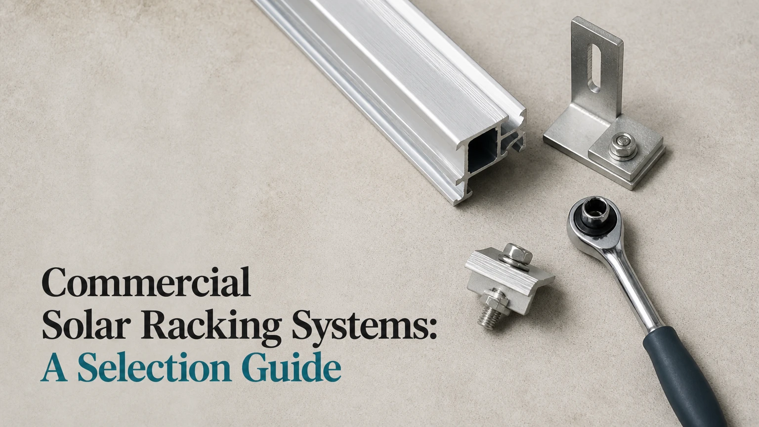
Commercial solar racking systems are engineered structures that secure photovoltaic modules to roofs, soil, parking areas, or elevated steel frames. The correct system transfers panel weight, wind uplift, snow, seismic forces, and maintenance loads into an approved structural path while preserving roof warranties, electrical bonding, drainage, and long-term service access.
Key Facts at a Glance
- Commercial solar racking commonly lasts 25-30 years, but roof membranes, sealants, and moving tracker parts may require earlier replacement.
- Ballasted rooftop arrays typically add about 2-6 pounds per square foot before project-specific ballast calculations.
- Typical racking hardware costs range from $0.08-$0.18 per watt DC, excluding modules, inverters, engineering, and major structural work.
- Driven piles, ground screws, concrete piers, and earth anchors are selected from soil conditions, pull-out testing, frost depth, corrosion exposure, and site access.
- Standing-seam clamps avoid roof penetrations, but the roof seam, panel orientation, clamp spacing, and manufacturer approval control the design.
- A racking system is only acceptable when its attachments, fasteners, grounding path, module clamps, and load calculations work together as one engineered assembly.
What Are Commercial Solar Racking Systems?
Commercial solar racking systems are the mechanical and structural assemblies between photovoltaic modules and the roof, ground foundation, carport frame, or tracker torque tube. The assembly normally includes attachment points, rails or beams, module clamps, fasteners, bonding hardware, cable management, and protective interfaces with the mounting surface.
The racking does more than hold modules at an angle. It transfers dead load from modules and steel or aluminum components into rafters, joists, purlins, concrete decks, piles, piers, or soil anchors. It also resists wind uplift, sliding, snow accumulation, seismic movement, thermal expansion, and occasional maintenance loading.
A 25-30-year racking life does not mean the entire solar installation remains maintenance-free for that period. Roof membranes, flashing, cable clips, tracker bearings, motors, coatings, and sealants can have shorter service intervals. A sound project therefore coordinates the solar design with the roof replacement cycle and the owner’s maintenance plan.
How Does the Structural System Work?
Commercial solar racking systems create a continuous load path from each module into the supporting building or ground structure. Engineers calculate the forces at connections, rails, splices, clamps, foundations, and supporting members rather than relying on a generic ballast quantity or an installer’s rule of thumb.
Wind is often the governing condition on rooftops. Wind pressure varies across interior, edge, and corner zones, so perimeter modules may require closer attachments, additional ballast, stronger fasteners, or a different array setback. Snow loading depends on ground snow values, roof geometry, drift conditions, module height, and local code provisions.
The design also checks concentrated reactions. A ballasted tray may distribute load over a broad roof area, while a mechanically attached bracket can impose a high local reaction at a rafter or purlin. The roof must resist both the total added weight and the localized force at every attachment.
The International Building Code and ASCE 7 provide the framework used by engineers for environmental loads in the United States. Project calculations should identify the adopted code edition, site wind speed, exposure category, risk category, snow load, seismic parameters, roof zones, and connection capacities.
What Components Make Up a Commercial Array?
The principal components are mounts or foundations, rails or primary beams, module clamps, fasteners, grounding hardware, and wire-management accessories. Each component must match the module frame, roof substrate, structural material, environmental exposure, and approved installation torque.
| Component | Common material or form | Primary function | Inspection concern |
|---|---|---|---|
| Roof attachment | Aluminum bracket, steel standoff, structural screw | Transfers forces into rafters, purlins, or deck | Pull-out, flashing, sealant, corrosion |
| Ballast tray | Aluminum or UV-resistant polymer | Holds concrete ballast and spreads reactions | Movement, drainage, membrane protection |
| Ground foundation | Driven steel pile, ground screw, concrete pier | Transfers rack forces into soil or concrete | Embedment, alignment, pull-out, corrosion |
| Rail or torque tube | Extruded aluminum, galvanized steel | Supports modules and distributes loads | Splice, deflection, thermal movement |
| End clamp | Stainless or coated aluminum | Secures array perimeter modules | Correct height, torque, edge distance |
| Mid-clamp | Stainless or coated aluminum | Secures adjacent module frames | Frame compatibility, torque, bonding |
| Bonding hardware | Listed lug, bonding clip, jumper | Establishes equipment grounding continuity | Listed combination, continuity test |
| Wire management | UV-rated clips, rail channel, conduit | Keeps conductors off abrasive surfaces | Sag, UV exposure, connector strain |
Module clamps require special attention because a clamp that fits the rail may still be incompatible with the module frame. Manufacturers specify clamping zones, minimum and maximum frame thickness, torque, end overhang, and sometimes rail span. Over-torquing can deform the frame or damage glass; under-torquing can allow vibration and movement.
Integrated bonding hardware also has limits. An anodized aluminum rail, steel attachment, module frame, and copper equipment grounding conductor require a listed bonding method. A visual connection is not proof of electrical continuity.
What Must Be Checked Before Design?
A commercial solar project should begin with a structural and roofing investigation, not a product catalog. The design team needs roof drawings, framing information, roof condition, warranty documents, geotechnical data where applicable, electrical scope, fire-access requirements, and the authority having jurisdiction’s current code requirements.
Roof age is a major economic variable. Installing an array on a membrane with only five years of expected service can force costly module removal and reinstallation. Roof consultants commonly recommend coordinating reroofing, membrane repairs, walk pads, drainage improvements, and attachment details before solar construction begins.
For ground arrays, soil conditions determine foundation economics. Driven piles may be fast in uniform soil but difficult in rock or buried debris. Ground screws can reduce concrete work, while concrete piers may be more predictable where soil variability, frost, or high overturning forces control.
Pre-Design Investigation Checklist
- Confirm roof type, membrane manufacturer, age, warranty, slope, drainage, and remaining service life.
- Identify rafters, joists, purlins, deck type, concrete thickness, and any previous structural modifications.
- Obtain site wind, snow, seismic, flood, wildfire, corrosion, and ice conditions.
- Verify module dimensions, frame thickness, clamp zones, weight, and approved mounting orientations.
- Map HVAC equipment, skylights, drains, parapets, fire lanes, access paths, and maintenance clearances.
- Test or document soil bearing, pile drivability, frost depth, groundwater, and corrosion conditions for ground mounts.
- Confirm utility interconnection, electrical pathways, rapid shutdown requirements, and equipment grounding design.
- Obtain written roofing-manufacturer approval for penetrations, flashing, walk pads, and attachment details.
OSHA’s fall-protection rule states, “The employer shall ensure that each employee on a walking-working surface with an unprotected side or edge that is 6 feet or more above a lower level is protected.” Racking installation must therefore include a site-specific fall-protection plan, not merely a hardware schedule.
Which Racking Type Fits the Site?
The best commercial racking type depends on roof capacity, wind exposure, roof warranty, land value, soil, energy profile, and maintenance access. Ballasted systems suit many low-slope roofs, while mechanically attached, ground-mounted, tracker, and carport systems solve different structural or operational constraints.
| Racking type | Typical setting | Typical tilt or height | Main advantage | Main limitation |
|---|---|---|---|---|
| Ballasted roof | Low-slope membrane roof | 5-15 degrees | Avoids routine roof penetrations | Adds about 2-6 lb/ft² of dead load |
| Mechanically attached roof | Membrane, metal, or structural deck | Roof-dependent | Lower ballast and high uplift capacity | Requires engineered penetrations |
| Standing-seam clamps | Metal standing-seam roof | Roof pitch, often 1-5 degrees | Non-penetrating attachment | Orientation follows roof geometry |
| Fixed ground mount | Open land, brownfield, utility site | 15-35 degrees, site-dependent | Easy service access and optimized tilt | Requires foundations, grading, and fencing |
| Single-axis tracker | Large open field | Approximately 0-60 degrees daily rotation | Higher production during extended daylight | Motors, bearings, controls, and row spacing add maintenance |
| Solar carport | Parking lot or garage deck | Usually 5-15 degrees | Uses parking space for generation | High steel, foundation, clearance, and collision costs |
When Is Ballasted Rooftop Racking Appropriate?
Ballasted rooftop racking is appropriate when the roof can carry the added weight and the wind design can resist sliding and uplift without excessive penetrations. Low-profile 5-10 degree arrays often reduce wind exposure and ballast compared with steeper configurations, although the final quantity requires engineering.
Ballast trays typically use concrete blocks, protective pads, wind deflectors, and friction between the assembly and roof surface. Protective interfaces must be compatible with TPO, PVC, EPDM, or modified-bitumen membranes. The design must preserve drainage and prevent ballast, pads, or rails from abrading the membrane.
Ballasted systems are not automatically safer for roofs. A weak roof, a slick membrane, high parapet turbulence, heavy snow, or a hurricane exposure may make mechanical attachment more suitable. Wind-tunnel testing or validated aerodynamic data can improve the design, but CFD alone does not replace code-based structural calculations and manufacturer limitations.
When Should a Roof Use Mechanical Attachments?
Mechanically attached racking is usually preferred when roof capacity is limited, wind uplift is severe, ballast would obstruct drainage, or the owner needs a lighter system. Attachments connect to rafters, joists, purlins, structural steel, concrete, or approved deck systems with screws, bolts, clamps, or engineered brackets.
Penetrations create a waterproofing responsibility. Flashing, pitch pans, compression seals, liquid-applied membranes, and target patches must match the roof assembly and warranty requirements. A roofing contractor or manufacturer-approved installer should control the waterproofing detail.
Mechanically attached systems are not automatically superior. Hundreds of penetrations can create inspection points, and an attachment that misses structural framing may have inadequate pull-out capacity. Every attachment requires verified location, fastener type, embedment, edge distance, and seal.
Are Standing-Seam Clamps a Good Commercial Option?
Standing-seam clamps are a strong option for compatible metal roofs because they grip the seam without drilling through the roof panel. The clamp must be approved for the exact seam profile, metal thickness, roof manufacturer, and design load, with spacing determined by engineering rather than visual symmetry.
The system usually mounts rails or module clamps directly to the seam clamps. Flush mounting reduces hardware and wind exposure, but it fixes the array near the roof pitch and may produce less favorable orientation. Thermal movement must remain possible because long metal roof panels and aluminum rails expand at different rates.
Standing-seam clamps are not appropriate for every ribbed or corrugated metal roof. A concealed fastener roof, structural seam, snap-lock seam, and mechanically seamed roof require different hardware. A clamp designed for one profile may damage another or fail to develop the specified capacity.
When Do Ground Mounts or Trackers Make Sense?
Ground-mounted fixed racks make sense when roof area is insufficient, land is available, maintenance access matters, or the owner wants a predictable tilt and orientation. Single-axis trackers become more attractive on large, unshaded sites where additional production during morning and afternoon hours has material value.
Typical tracker energy gains are often reported at 15%-30% over fixed-tilt systems, but the result varies with latitude, row spacing, terrain, backtracking, albedo, weather, and the comparison tilt. Tracker economics must include motors, controllers, bearings, spare parts, row-to-row shading, wind stow behavior, and specialized maintenance.
Ground systems also require security and environmental planning. Fencing, vegetation control, snow clearance, drainage, livestock, agricultural use, glare, erosion, and underground utilities can change the preferred foundation and layout.
What Does Commercial Solar Racking Cost?
Typical commercial racking hardware costs about $0.08-$0.18 per watt DC, while mechanical installation labor commonly adds $0.03-$0.08 per watt. These figures exclude unusual foundations, roof reinforcement, reroofing, engineering, permitting, trenching, trackers, carport steel, and major electrical work.
A 500-kilowatt rooftop project might therefore show roughly $40,000-$90,000 in basic racking hardware and $15,000-$40,000 in mechanical installation labor before project-specific structural or roofing costs. The actual price depends heavily on module layout, attachment density, roof access, ballast, freight, steel prices, and local wages.
| Cost element | Typical commercial range | Main cost driver | Usually excluded |
|---|---|---|---|
| Racking hardware | $0.08-$0.18/W DC | Material, ballast, clamps, rails | Structural reinforcement |
| Mechanical labor | $0.03-$0.08/W DC | Roof access, attachment count, crew rate | Electrical labor |
| Engineering and permits | 4-12 weeks | Structural review, AHJ, revisions | Utility upgrade work |
| On-site construction | 2-6 weeks | Array size, roof complexity, weather | Long-lead equipment delays |
| Ground foundations | $0.10-$0.40/W, typical planning range | Soil, piles, concrete, grading | Land acquisition and fencing |
| Solar carport structure | $0.30-$0.80/W, typical planning range | Steel, foundations, clearance | Parking-lot reconstruction |
The U.S. Department of Energy’s Federal Energy Management Program identifies system cost categories such as design, permitting, installation, and balance-of-system equipment, which is why racking should not be compared with a module price alone. GreenLancer reports a broad commercial solar project benchmark of approximately $1.40-$1.80 per watt DC, but location, financing, labor, interconnection, and scope can move the total substantially.
How Is a Commercial Racking System Installed?
A typical commercial installation takes 2-6 weeks on site for a moderate project, while engineering, procurement, roofing coordination, and permitting can take 4-12 weeks. The governing success factor is accurate structural information before crews place attachments, ballast, or foundations.
- Survey the site. Record roof zones, framing, obstructions, membrane condition, access routes, drainage, soil conditions, and electrical pathways.
Checkpoint: The layout identifies every attachment, ballast pad, foundation, setback, and service aisle.
Common mistake: Designing from aerial imagery without opening roof or structural records. - Complete structural calculations. Determine dead load, wind uplift, snow, seismic forces, rail deflection, connection capacity, and foundation reactions using the adopted code.
Checkpoint: The engineer stamps or approves calculations where required by the jurisdiction.
Common mistake: Applying a generic ballast table outside its wind, roof, or module assumptions. - Coordinate the roof and foundation work. Repair membranes, confirm flashing details, mark structural members, clear vegetation, and verify underground utilities.
Checkpoint: The substrate is sound and the installation crew has approved attachment locations.
Common mistake: Installing over an aging membrane that cannot support the intended warranty period. - Install bases, attachments, or foundations. Place protective pads and ballast trays, install roof attachments, drive piles, set ground screws, or pour concrete piers according to the engineered plan.
Checkpoint: Each connection meets location, embedment, alignment, and torque requirements.
Common mistake: Substituting fasteners or shifting an attachment to avoid an obstruction without engineering approval. - Build rails and primary steel. Install aluminum rails, steel beams, torque tubes, splices, braces, and expansion provisions.
Checkpoint: Rail elevation, span, alignment, and splice gaps match the design.
Common mistake: Creating long, continuous metal runs without the manufacturer’s thermal-movement detail. - Mount and torque modules. Install end clamps, mid-clamps, module-level equipment, and approved bonding hardware using calibrated tools.
Checkpoint: Clamp engagement, torque marks, frame support, and module orientation pass inspection.
Common mistake: Treating a visually tight clamp as proof of correct torque. - Manage conductors and verify grounding. Secure cables with UV-rated clips, protect connectors, install equipment grounding conductors, and test continuity.
Checkpoint: No cable contacts the roof, sharp steel, standing water, or unsupported rail edge.
Common mistake: Using ordinary plastic zip ties that become brittle under ultraviolet exposure.
Which Design Mistakes Cause the Most Problems?
The most expensive commercial racking failures usually begin with mismatched assumptions rather than defective aluminum. Roof warranties, local wind zones, fastener capacity, thermal movement, cable support, and module clamp instructions deserve review before construction.
| Failure mode | Typical cause | Observable symptom | Corrective action |
|---|---|---|---|
| Roof leak | Unapproved penetration or failed flashing | Water staining below attachment | Stop work, inspect membrane, repair with approved detail |
| Ballast movement | Incorrect friction, wind zone, or pad placement | Trays shift after storms | Recalculate, inspect membrane, add approved restraint |
| Galvanic corrosion | Dissimilar metals without isolation | White corrosion, rust, loose fasteners | Replace incompatible parts and add listed isolation |
| Cable abrasion | Unsupported conductors on roof or steel | Insulation wear or RISO fault | Replace damaged cable and add UV-rated supports |
| Module microcracking | Uneven rails or excessive clamp torque | Hot spots, low string output | Recheck rail plane, torque, and module condition |
| Drainage blockage | Ballast, pads, or cables across drains | Ponding or debris accumulation | Restore flow and revise layout or maintenance access |
An expert rule is to treat roof drainage as a structural design constraint. A rack that satisfies wind calculations can still damage a building if pads, ballast, or cables redirect water toward seams, drains, scuppers, or low points.
Another rule concerns thermal movement. Do not specify a maximum rail run from a generic 30-60-foot assumption without checking the racking manufacturer’s splice and expansion instructions, because rail alloy, roof temperature, attachment type, and climate alter the required detail.
A third rule is to separate module warranty requirements from racking strength. A connection can resist wind while still violating the module manufacturer’s clamp zone or torque requirement. That mismatch can create frame deformation, glass stress, or a denied warranty claim.
How Should Owners Choose by Facility Type?
Warehouses with broad, low-slope roofs often favor low-profile ballasted arrays when structural capacity, wind calculations, drainage, and roof warranty permit the added load. A mechanically attached system may be better where ballast exceeds capacity or edge-zone uplift becomes expensive.
Manufacturing facilities with standing-seam metal roofs often benefit from approved seam clamps and flush mounting. The decision changes when the roof has incompatible seams, high corrosion exposure, process emissions, fragile coatings, or a planned replacement.
Rural businesses and energy developers frequently compare fixed ground mounts with single-axis trackers. Fixed racks offer simpler maintenance and lower mechanical complexity, while trackers can increase production where land, irradiance, and electricity pricing justify the additional equipment.
Parking facilities may use solar carports when land is scarce or shade has operational value. Carports require vehicle-clearance analysis, column protection, drainage, lighting coordination, fire access, snow drift review, and foundations designed for impact and overturning forces.
What Maintenance Does Racking Require?
Commercial racking maintenance should include annual visual inspections and additional reviews after severe wind, hail, heavy snow, flooding, or construction activity. Inspectors should check loose clamps, corrosion, cable support, roof leaks, ballast movement, blocked drains, tracker alarms, foundation settlement, and grounding continuity.
Ballasted roofs need membrane and drainage inspections because debris can collect beneath trays and pads. Ground mounts need vegetation control, fence inspection, erosion monitoring, and foundation checks. Trackers require manufacturer-specific lubrication, firmware, motor, bearing, stow, and torque-tube inspections.
A ground fault or insulation-resistance alarm requires electrical troubleshooting rather than a racking-only repair. Isolate the affected circuit under qualified procedures, inspect conductors and connectors, test insulation, and replace damaged cable before returning the string to service.
FAQ
Can solar racking damage a commercial roof?
Commercial solar racking can damage a roof when attachments, ballast pads, flashing, drainage, or maintenance access are poorly designed. A listed system installed over a sound membrane with roofing-manufacturer approval can reduce risk, but no mounting method eliminates inspection and warranty coordination.
Does a commercial roof need reinforcement for solar panels?
A commercial roof needs reinforcement when its existing members, deck, connections, or foundations cannot resist the calculated total and localized solar loads. Ballasted arrays may require reinforcement because of added dead weight, while attached arrays can require reinforcement at concentrated attachment reactions.
Is a tracker better than a fixed ground mount?
A tracker is better when additional energy production justifies motors, controls, maintenance, row spacing, and higher capital cost. A fixed ground mount is usually better when simplicity, predictable maintenance, difficult terrain, small project size, or lower operational risk outweighs the tracker’s potential production gain.
How long does commercial solar racking last?
Commercial solar racking commonly lasts 25-30 years when corrosion protection, fastener compatibility, drainage, and maintenance remain adequate. Roof membranes, sealants, tracker components, cables, and module electronics may require replacement before the rails or primary steel reach the end of their service life.
What wind speed can commercial solar racking withstand?
Commercial solar racking does not have one universal wind-speed rating. Capacity depends on site wind speed, exposure, risk category, roof zone, array geometry, attachment spacing, ballast, module dimensions, and the manufacturer’s tested or engineered configuration under the adopted building code.
Should a commercial solar array be removed before reroofing?
A commercial solar array should usually be removed before full roof replacement when the roofing contractor cannot maintain the membrane warranty or access the complete roof surface. Removal and reinstallation costs should be included in the original financial model if the roof has limited remaining life.
The Bottom Line
Commercial solar racking systems should be selected from the site’s structural capacity, wind and snow exposure, roof warranty, soil, maintenance plan, and energy objective. Ballasted roofs prioritize nonpenetration, attached roofs reduce weight, standing-seam clamps protect compatible metal roofs, ground mounts improve access, trackers increase production potential, and carports convert parking infrastructure into generation space.
The lowest hardware price is rarely the lowest project cost. A durable design verifies the load path, waterproofing, corrosion control, module clamp requirements, grounding, drainage, thermal movement, construction access, and future roof or foundation work before procurement. That process produces commercial solar racking systems capable of supporting a 25-30-year photovoltaic investment.