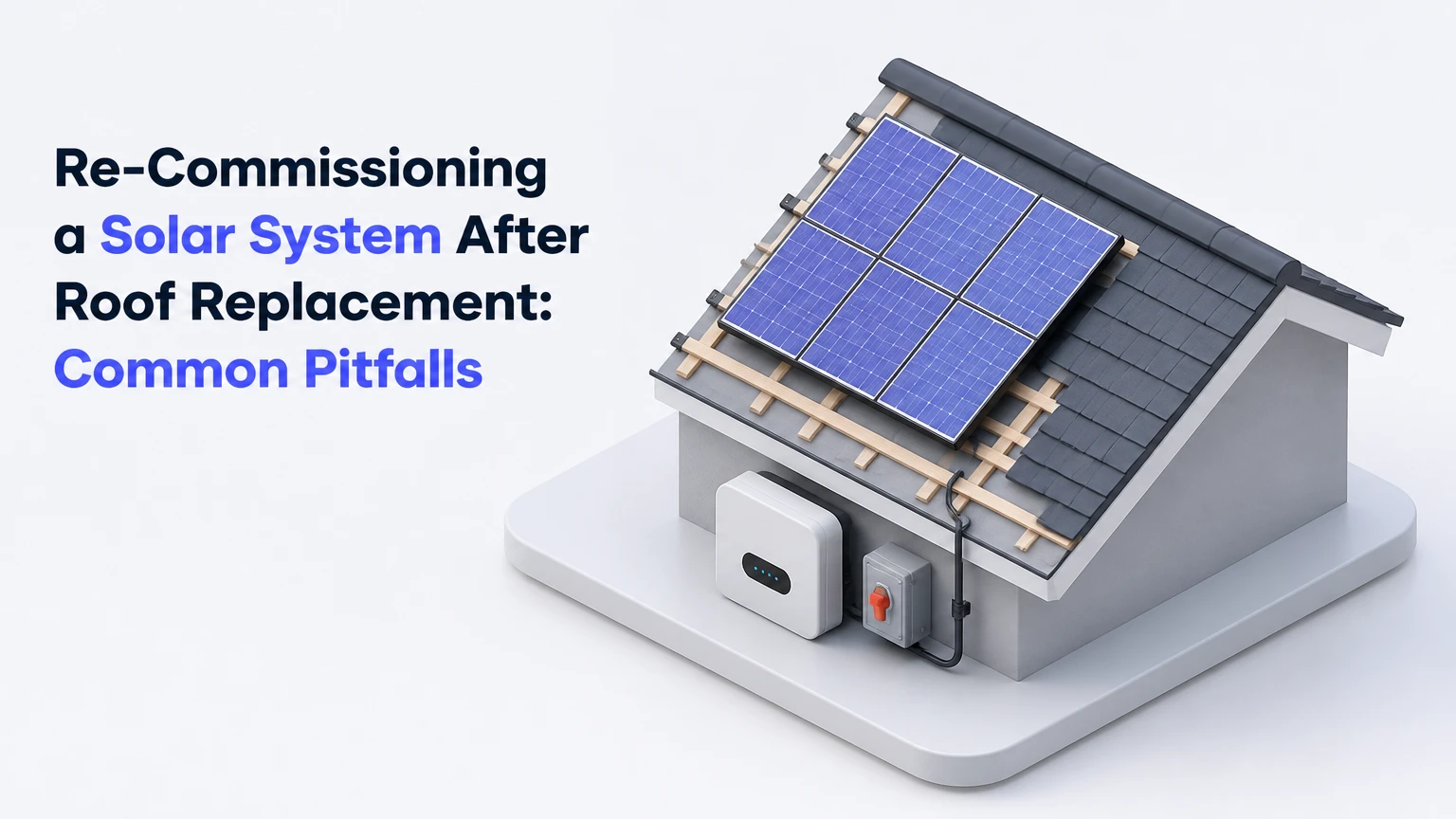
Re-commissioning a solar system after a roof replacement is the documented inspection, electrical testing, controlled energization, and performance verification required after photovoltaic equipment has been disturbed and reinstalled. The most serious failures are hidden cable damage, incompatible connectors, incorrect grounding, lost MLPE mapping, and battery or CT wiring errors that allow a system to operate while remaining unsafe or incorrectly monitored.
Key Facts at a Glance
A system that powers on has not necessarily passed commissioning; insulation, polarity, grounding, labeling, monitoring, and production checks still require verification.
Insulation resistance limits, test voltage, torque values, and energization order come from the applicable code, equipment manual, and authority having jurisdiction, not one universal internet checklist.
SolarEdge optimizer voltage behavior and Enphase microinverter discovery are architecture-specific tests, not interchangeable procedures.
Typical residential post-roof commissioning takes 2-5 hours when equipment is accessible and no defects require repair.
Typical isolated commissioning costs $400-$900; full detach and reset commonly costs $2,500-$6,000 for a 6-12 kW residential system.
The homeowner should receive measured test results, photographs, updated equipment maps, monitoring confirmation, and permit or utility records before final payment.
What Re-Commissioning Means
Re-commissioning begins after the array has been mechanically reset, but it is broader than switching the inverter back on. A qualified technician verifies that roof attachments, modules, racking, conductors, connectors, grounding, disconnects, inverter settings, communications, and production data still match the approved system design.
The work normally follows this chain:
- Document the original system and isolate equipment.
- Remove and store modules and electrical components safely.
- Replace the roof and verify attachment locations.
- Reinstall racking, modules, wiring, and balance-of-system equipment.
- Perform cold electrical and mechanical tests.
- Energize equipment under the manufacturer’s procedure.
- Confirm monitoring, grid interaction, battery behavior, and production.
- Record results and close required warranty, permit, and utility actions.
The National Electrical Code, especially Article 690 in NFPA 70, provides installation and safety requirements, while IEC 62446-1 provides a framework for photovoltaic system documentation, verification, and commissioning tests. Local amendments and the authority having jurisdiction can impose additional requirements.
What commissioning is not
Re-commissioning is not a visual glance, an inverter screenshot, or a claim that “the panels are making power.” It also does not prove that a roof is watertight. Roofing quality and electrical safety overlap around penetrations and flashing, but each requires separate evidence.
A roof contractor may warrant shingles or flashing without warranting DC insulation resistance. A solar contractor may warrant electrical reconnection without warranting roofing workmanship. The contract should identify both responsibilities.
Why Are Post-Roof Solar Systems High Risk?
The highest-risk defects are created during handling, fastening, and reconnection rather than during ordinary operation. A module frame can crush a cable against a rail, a connector can remain partly engaged, and a ground-bonding device can lose contact after rails are moved.
The danger is often invisible. A cable jacket can pass a casual inspection yet fail when moisture reaches a compression point. A system can also produce normal midday power while one unused string contains a latent insulation fault.
The National Renewable Energy Laboratory’s operations and maintenance guidance emphasizes documentation, preventive inspection, electrical testing, and consistent fault records because performance and safety problems often require comparison with the original design baseline.
The four evidence categories
| Evidence category | Required example | Failure consequence | Verification record |
|---|---|---|---|
| Mechanical | Rail and clamp torque recorded in inch-pounds or newton-metres | Module movement, roof damage, loose bonding | Torque log and photographs |
| Electrical | Polarity, Voc, insulation resistance, and grounding results | Arcing, shock hazard, inverter fault | Meter serial number and readings |
| Digital | Inverter, optimizer, microinverter, and gateway inventory | Wrong panel data, missing devices, false alarms | Updated equipment map |
| Administrative | Permit, utility, warranty, and insurance documents | Delayed approval or disputed liability | Signed commissioning package |
What Should Happen Before Power Is Applied?
A qualified solar electrician should complete the first three inspection stages with the system isolated from the grid and solar array. The technician should use the approved one-line diagram, module layout, equipment manuals, and original commissioning data rather than relying on memory.
Step 1: Inspect the reset installation
Check every module, rail, attachment, clamp, flashing detail, conduit, junction box, disconnect, and exposed conductor before testing. Clamp torque is manufacturer-specific; a 10-15 ft-lb figure may apply to some hardware but must not replace the racking supplier’s instructions.
Confirm that:
- Roof attachments land in the intended structural members.
- Flashing is installed according to the roofing and mounting-system instructions.
- Modules have no cracked glass, bent frames, damaged junction boxes, or impact marks.
- Conductors are supported by approved clips and do not rest on shingles or sharp metal.
- Cable loops have adequate clearance and do not violate the connector manufacturer’s bend radius.
- Connectors are fully mated and use approved same-family components.
- Equipment grounding and bonding paths are continuous.
- Labels remain legible at the array, inverter, disconnects, combiner, and service equipment.
Take photographs before the array becomes difficult to inspect. Photographs cannot replace measurements, but they establish the condition of flashing, cable routing, and hardware at handover.
Step 2: Perform isolation and insulation tests
An insulation resistance test checks leakage between current-carrying conductors and ground. Test voltage and acceptance criteria must follow the equipment manufacturer, system voltage, governing code, and testing standard; 1,000 V DC and a 1 MΩ pass value are not universal requirements.
Some inverters, rapid shutdown devices, optimizers, surge-protection devices, batteries, and communications equipment can be damaged by an incorrectly applied Megger test. The technician must isolate sensitive electronics before connecting the instrument.
| Test item | Typical method | Why the value varies | Required response |
|---|---|---|---|
| DC insulation resistance | Insulation tester at manufacturer-specified voltage | Array voltage and connected electronics differ | Stop if the value is low or unstable |
| Conductor polarity | Rated DC meter or polarity tester | String design determines test points | Correct before connector mating |
| Equipment grounding | Continuity or low-resistance method | Bonding architecture differs by equipment | Repair loose or missing bonds |
| Rapid shutdown function | Manufacturer commissioning tool | Module-level shutdown design varies | Test each required circuit |
| Battery insulation | Battery or inverter service procedure | High-voltage storage systems require special isolation | Use trained storage technician |
IEC 62446-1 provides test concepts for PV systems, but a local code inspector or manufacturer manual may define the accepted procedure. A low reading should trigger fault location, not a quick “pass” based on a generic threshold.
Step 3: Verify cold electrical values
Measure each string’s open-circuit voltage, polarity, and, where the procedure permits, current. Compare Voc with the expected module count and temperature-adjusted design value, and compare similar strings under similar irradiance.
Short-circuit current testing deserves special care. A technician should not improvise by placing an ordinary multimeter across a live high-voltage string. The instrument must be appropriately rated, the test method must be approved, and current measurement may use a calibrated DC clamp meter or another manufacturer-approved method.
| Cold check | Typical reference | What a deviation suggests | Immediate action |
|---|---|---|---|
| String Voc | Expected module count multiplied by temperature-adjusted module Voc | Open connector, wrong module count, bypass diode issue | Isolate and trace the string |
| String current | Similar strings under the same irradiance | Shade, open circuit, damaged module, poor connection | Compare with adjacent strings |
| Polarity | Positive and negative match the one-line diagram | Reversed leads or crossed connectors | Do not connect to inverter |
| Ground continuity | Low resistance through the intended bonding path | Loose lug, missing bonding hardware, anodized contact | Repair and retest |
| DC voltage at inverter | Matches array design and MPPT allocation | Wrong string input or field wiring error | Correct before energization |
A 5% comparison tolerance may be a useful field screening rule for similar strings, but it is not a universal pass/fail limit. Temperature, irradiance, module mismatch, soiling, and measurement uncertainty affect results.
How Should the System Be Energized?
The technician should energize the array only after mechanical, polarity, insulation, grounding, and protective-device checks pass. The exact sequence must come from the inverter and battery manufacturer because AC-coupled, DC-coupled, rapid-shutdown, and hybrid systems do not share one safe sequence.
A common grid-tied sequence includes closing the required AC disconnect or breaker, applying DC according to the inverter manual, observing startup diagnostics, and waiting for grid qualification. Some manufacturers specify DC first, while others specify AC first. The written manual controls.
Record:
- Inverter model, firmware, and serial number.
- Grid profile and utility voltage.
- Startup alarms and their clearing time.
- AC voltage and frequency.
- DC input or MPPT values.
- Rapid shutdown response.
- Battery state of charge and operating mode, if installed.
IEEE 1547 addresses interconnection and grid-support behavior for distributed energy resources, but utility approval and inverter certification determine the settings applicable to a particular installation.
Which System Type Changes the Risk?
String inverters concentrate many DC circuits at one location, optimizer systems add module-level electronics and mapping, microinverters place conversion equipment on the roof, and hybrid systems add batteries, communications, and current-transformer configuration. The correct commissioning emphasis follows the architecture.
| System architecture | Main reconnection risk | Priority verification | Mapping or configuration issue |
|---|---|---|---|
| String inverter | Damaged high-voltage DC cable | Insulation, polarity, Voc, MPPT allocation | String landed on wrong MPPT |
| DC optimizer system | Lost optimizer identity or wiring fault | Optimizer discovery and manufacturer-specific safe-voltage test | Serial number assigned to wrong module |
| Microinverter system | Roof-level AC connector or trunk fault | Device discovery, AC voltage, branch circuit, grid profile | Microinverter serial number misplaced |
| Hybrid battery system | CT, communication, or isolation error | Battery sequence, CT direction, phase matching | Battery mode or consumption data incorrect |
SolarEdge optimizer systems
SolarEdge equipment has model-specific commissioning behavior. Some systems use a safe-voltage or optimizer discovery procedure, but “exactly 1 V per optimizer” should not be treated as a universal rule for every SolarEdge generation or optimizer model.
The technician should use the SolarEdge installation and commissioning documentation for the installed equipment, confirm the number of optimizers, reconcile serial numbers with the physical layout, and complete pairing through the approved installer platform.
Enphase microinverter systems
Enphase commissioning requires confirmation that the IQ Gateway or Envoy discovers the expected microinverter inventory and that the digital array map matches the physical roof. The installer should also verify branch circuits, neutral and equipment-grounding conductors where applicable, communications, and the configured grid profile.
Enphase installation documentation defines equipment-specific wiring and commissioning requirements. Serial-number stickers should be photographed before modules are moved, because recovering an incorrect map after reinstallation can require roof access again.
Battery and hybrid systems
Battery systems add stored energy that may remain available when the grid is disconnected. A qualified storage technician must follow the manufacturer’s shutdown and startup procedure, verify CT orientation and phase association, confirm communication loops, and test backup behavior without creating an unsafe islanding condition.
For Tesla Powerwall and comparable systems, the inverter, gateway, battery, service equipment, and monitoring portal must agree about grid status and operating mode. A battery that charges from the grid unexpectedly may indicate a configuration or CT problem, not a defective battery.
What Are the Common Pitfalls?
The most common post-roof solar failures are connector incompatibility, pinched conductors, incorrect device mapping, incomplete grounding, reversed CTs, and missing documentation. These defects differ in visibility, so a functioning inverter cannot rule them out.
Pitfall 1: Mixing connector brands
A connector described as “MC4-compatible” is not automatically approved for mating with a genuine Stäubli MC4 connector. The connector manufacturer’s installation instructions and listing determine compatibility.
A mismatched pair can create contact resistance and water-entry paths. Thermal imaging may reveal a hot connection under load, but a normal thermal image does not certify connector compatibility or insulation integrity. Stäubli’s MC4 instructions require compatible components and correct assembly methods.
Pitfall 2: Pinching DC conductors under rails
A conductor trapped between a module frame and aluminum rail can suffer jacket damage that appears only after tightening. Ground-fault or low-insulation alarms may occur immediately, intermittently during rain, or weeks after commissioning.
The correct recovery is to isolate the affected circuit, locate the damaged section with approved testing, replace the conductor or connector when required, and retest. Electrical tape over a crushed PV wire is not an equivalent repair.
Pitfall 3: Losing MLPE mapping
A physical module map and an online monitoring map can disagree after a detach and reset. The portal may report module 3 as underperforming when the actual issue is at the physical location assigned to module 18.
Before final handover, scan or photograph every serial number, compare the inventory with the approved layout, and verify that a controlled module-level test produces data at the expected location.
Pitfall 4: Reusing damaged connectors or hardware
Reusing a connector with a cracked latch, heat discoloration, damaged seal, or contaminated contact can create a future failure. Reusing mounting hardware is also inappropriate when the manufacturer specifies single-use fasteners or when threads, washers, or bonding surfaces are damaged.
Pitfall 5: Reversing CT clamps
A reversed consumption CT can make household load appear negative, make production data look implausible, or cause a battery to charge and discharge at the wrong times. The arrow orientation, phase assignment, and terminal polarity must match the inverter or gateway instructions.
Pitfall 6: Accepting “powering on” as commissioning
An inverter screen showing “producing” proves only that some operating conditions were met. It does not establish insulation resistance, correct device mapping, roof attachment quality, or complete utility documentation.
How Much Does Re-Commissioning Cost?
Typical isolated residential re-commissioning costs $400-$900 and require 2-5 hours on site. A full detach and reset for a 6-12 kW system commonly costs $2,500-$6,000 because removal, protected storage, roof coordination, reinstallation, testing, and travel are separate labor components.
| Scope | Typical residential cost | Typical time | Included work |
|---|---|---|---|
| Testing only | $400-$900 | 2-5 hours | Inspection, electrical tests, startup, report |
| Minor repair plus testing | $700-$1,800 | 3-8 hours | Testing plus connectors, cable, labels, or bonds |
| Full detach and reset | $2,500-$6,000 | 1-3 days total | Removal, storage, reinstallation, commissioning |
| Battery-equipped reset | $3,500-$8,000 | 1-3 days | Solar work plus battery isolation and configuration |
Commercial systems of 50-200 kW or larger often require $1,500-$4,500 or more for isolated commissioning and $15,000-$45,000 or more for full detach and reset. Roof access, crane use, multiple arrays, engineering review, and utility witness testing can move the price substantially.
A quote should separate removal, storage, replacement materials, roof repairs, electrical testing, monitoring repair, permit work, and warranty administration. The original installer may price higher because it assumes greater warranty liability.
Who Should Perform the Work?
The original solar installer is usually the strongest choice when available, licensed for the jurisdiction, and willing to document the work. A qualified detach-and-reset specialist is a practical alternative when the original company is unavailable, but the homeowner should confirm manufacturer certifications and warranty terms before signing.
| Provider | Typical strength | Main risk | Selection requirement |
|---|---|---|---|
| Original solar installer | Original design and warranty records | Scheduling delay or higher price | Written warranty continuation |
| Solar detach specialist | Efficient removal and reset experience | May not support every inverter brand | Brand-specific commissioning capability |
| Roofing contractor with solar crew | Coordinated roof schedule | Electrical testing may be incomplete | Dedicated licensed solar electrician |
| Independent electrical contractor | Electrical troubleshooting | Limited roof and MLPE experience | PV, storage, and mounting references |
The roofing contractor should not reconnect PV equipment unless the company has the required electrical licensing, qualified personnel, and documented experience with the installed architecture. A roofer can coordinate flashing while a solar electrician performs electrical isolation, testing, and energization.
Questions to put in the contract
- Who owns responsibility for roof leaks caused by array penetrations?
- Who owns responsibility for damaged modules, connectors, optimizers, and inverters?
- Will the original workmanship warranty remain valid?
- Which measured values will appear in the final report?
- Who will correct a failed insulation or grounding test?
- Will monitoring maps and serial numbers be updated?
- Who will handle permit amendments and utility approval?
- What happens if concealed damage is discovered after removal?
What Should the Final Commissioning Package Contain?
The final package should contain enough evidence for a future technician, insurer, utility, or warranty department to reconstruct the system condition. A single certificate without measurements is weak evidence.
| Document or record | Minimum content | Owner benefit | Retention target |
|---|---|---|---|
| Updated one-line diagram | Equipment, disconnects, circuits, ratings | Supports future service and inspections | System life |
| Physical array map | Module, optimizer, or microinverter locations | Prevents mapping disputes | System life |
| Test log | Voc, current method, insulation, grounding, AC values | Shows measured commissioning status | At least warranty period |
| Photo set | Flashing, clamps, cable routing, labels, screens | Establishes post-work condition | At least warranty period |
| Monitoring record | Device inventory, portal status, production baseline | Enables performance comparison | System life |
| Administrative file | Permit, utility, warranty, invoices | Supports compliance and claims | Local legal requirement |
The report should identify the technician, company license where applicable, test-instrument model and calibration status, date, weather conditions, array configuration, failed tests, repairs, and final results.
Edge Cases That Change the Process
Roof replacement can alter more than the surface beneath the array. A new roof may change attachment locations, array geometry, shade exposure, conduit routing, or the approved electrical plan.
Older systems
Systems more than 10 years old may contain discontinued inverters, obsolete connectors, degraded roof flashings, or monitoring hardware that cannot be re-paired. The homeowner should obtain a repair-versus-replacement quote before removal if replacement parts are scarce.
Partial roof replacement
If only one roof plane is replaced, the affected subarray still requires testing. Shared conduits, combiners, and MPPT inputs can spread the consequence of a local reconnection error to unaffected modules.
Storm or impact damage
A roof claim following hail, wind, or falling debris requires module inspection beyond the roof contractor’s scope. Electroluminescence testing, insulation testing, and IV-curve analysis may be appropriate when visual inspection cannot establish cell or bypass-diode condition.
Permit or utility changes
Moving modules, changing attachment locations, replacing an inverter, altering system capacity, or changing a battery configuration may require an amended permit or utility submission. The installer should confirm requirements with the local authority before work begins, not after the system is energized.
Common Troubleshooting Decisions
Use alarms and production data to guide isolation, but do not bypass protective devices or repeatedly reset a faulting inverter. Persistent ground-fault, isolation, arc-fault, rapid-shutdown, or battery alarms require qualified service.
| Symptom after reset | Likely causes | Safe diagnostic direction | Do not do |
|---|---|---|---|
| Inverter shows isolation fault | Pinched cable, wet connector, damaged module | Isolate strings and test per manual | Keep resetting the inverter |
| One string has low Voc | Open connector, wrong module count, polarity issue | Compare with design and adjacent strings | Plug unknown leads together |
| Monitoring misses devices | Lost serial map, gateway communication fault | Reconcile physical inventory | Accept an incomplete portal |
| Negative consumption | CT reversal or wrong phase | Check arrows and phase terminals | Change settings without measurements |
| Battery charges unexpectedly | CT, mode, or communication error | Follow battery commissioning procedure | Disable protection logic |
| Hot connector under load | Poor crimp, incompatibility, looseness | De-energize and replace approved parts | Spray or tape the connector |
How Long Does the Work Take?
A straightforward residential commissioning visit usually takes 2-5 hours after the array is fully reset and accessible. Full detach and reset commonly occupies one to three working days, excluding roof delays, permit inspections, replacement-part shipping, and utility approval.
Weather can extend the schedule because wet roofs, rain, lightning, and poor irradiance affect safe access and certain measurements. Battery isolation, difficult attic routes, multiple roof planes, and missing original records add time.
The schedule is ready for closeout when the system passes electrical checks, all devices appear in monitoring, the production result is plausible for the weather, documentation is complete, and required administrative approvals are identified.
The Bottom Line
Re-commissioning a solar system after a roof replacement is a verification process, not a power-on event. The safest outcome requires a qualified solar electrician to compare the rebuilt array with its design, test insulation and grounding using equipment-specific procedures, confirm connector and MLPE integrity, verify monitoring and battery behavior, and provide a complete record before payment.
Do not accept generic test thresholds, an unverified MC4-compatible connector, an incomplete optimizer map, or a screenshot showing production as proof of completion. The common pitfalls are preventable when the contract assigns roof and electrical responsibilities separately and the commissioning report records actual measurements.
Frequently Asked Questions
Can a roofing company reconnect solar panels?
A roofing company can coordinate roof work, but reconnection should be performed by personnel holding the electrical qualifications required in the jurisdiction and trained on the installed PV architecture. The contract should name the solar electrician, testing scope, warranty responsibility, and party responsible for correcting failed insulation, grounding, monitoring, or battery tests.
Is re-commissioning required after every roof replacement?
Re-commissioning is warranted whenever modules, racking, conductors, connectors, inverters, disconnects, batteries, or monitoring equipment are removed or disturbed. Local permitting rules determine whether formal inspection or utility notification is mandatory, while equipment manufacturers may require documented commissioning to preserve warranty support.
What if the original solar installer has closed?
A qualified PV service company can review the original permit, one-line diagram, equipment records, and monitoring data before performing the reset. Select a contractor with the installed inverter and battery certifications, require a baseline inspection, and obtain written confirmation about which original warranties remain transferable.
Can solar panels be reinstalled on a different roof section?
Solar panels can be moved to another roof section only after confirming structural capacity, attachment details, fire-access clearances, shade conditions, conductor lengths, voltage design, and permit requirements. Moving the array can change the approved electrical design and may require new racking, conduit, rapid-shutdown equipment, or utility documentation.
Why is production lower after the roof replacement?
Lower production can result from changed roof orientation, new shade, incorrect string allocation, missing microinverters or optimizers, soiling, damaged modules, monitoring errors, or weather differences. Compare measured string or device data with irradiance and the original baseline before concluding that the roof replacement itself reduced output.
What should homeowners do if the installer skips testing?
Ask for the commissioning report, measured test values, equipment map, photographs, and permit or utility records before approving final payment. If the installer refuses or cannot provide them, hire an independent licensed PV professional to inspect the system and document any safety or warranty issue.