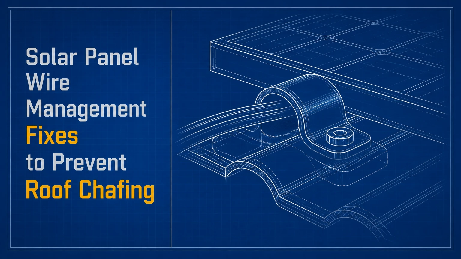
Solar panel wire management fixes prevent roof chafing by lifting PV cables off shingles, eliminating sharp-edge contact, and securing conductors with UV-rated clips or ties without crushing the insulation. The correct repair also preserves bend radius, avoids connector strain, protects roof penetrations, and uses components listed for the cable and installation environment.
Key Facts at a Glance
Solar cables should not rest on abrasive shingles, roof membranes, flashing, or unprotected metal edges.
PV wire attachment must support the cable without compressing, piercing, or sharply bending the insulation.
A typical field target is 300-450 mm between supports, but the racking, cable, conduit, and local code instructions control.
A visibly nicked or flattened conductor requires qualified electrical evaluation, not tape wrapped over the damage.
Unused connectors should remain mated or use manufacturer-approved protective caps, never loose in standing water.
Cable management hardware must tolerate outdoor UV, temperature cycling, wind movement, and the expected system life.
Why Roof Chafing Happens
Solar panel cable chafing occurs when repeated movement removes insulation against a rough or sharp surface. Wind-induced vibration, thermal expansion, snow loading, ice movement, and installer foot traffic can turn a small contact point into a fault over months or years.
Common contact points include shingle granules, exposed fastener heads, rail ends, module-frame corners, flashing edges, conduit fittings, and roof-mounted equipment. A cable can look correctly routed during installation yet sag after a nylon tie cracks or a clip releases.
The U.S. Department of Energy identifies unsupported or poorly routed PV cables as a reliability and safety concern because damaged insulation can expose energized conductors and create ground-fault conditions. The mechanism is simple: abrasion reduces the insulation wall, moisture reaches the conductor, and current leakage or arcing becomes more likely.
What Damage Should You Look For?
Use a bright flashlight and photograph every suspect section before touching the wiring. Look for polished or flattened insulation, white stress marks on black cable, exposed braid or copper, melted areas, cuts at clip mouths, loose connectors, and cable sections that move independently in wind.
A light surface scuff is not automatically a failed cable, but a groove that catches a fingernail deserves professional assessment. Exposed conductor strands, burned insulation, repeated inverter ground-fault alarms, or water inside a connector justify immediate electrical isolation by a qualified person.
Can Solar Cables Touch Shingles?
Solar cables should not lie directly on shingles. Shingles are abrasive, their surface changes with heat and moisture, and cable movement can wear insulation even when the roof appears smooth from the ground.
The same rule applies to synthetic membranes, coated metal roofing, tile edges, and roof flashing. A cable may cross a roof briefly during installation, but permanent routing should use the module frame, mounting rail, approved cable clips, or a protected raceway.
The U.S. National Electrical Code requires PV wiring to be secured and protected from physical damage, while the exact installation method depends on the wiring system, roof configuration, and authority having jurisdiction. IEC 62548-1 also addresses PV array wiring, mechanical protection, routing, and cable support. Code compliance is not a substitute for abrasion prevention. A technically permitted cable route can still be a poor long-term maintenance choice if it rubs continuously.
How Do You Fix Chafing Solar Panel Wires?
The reliable repair sequence has seven stages: de-energize safely, inspect the cable, remove the abrasion source, reroute the conductor, install compatible supports, verify connectors and bend radius, then document the correction. A small residential correction typically takes 30-90 minutes after safe access is established; cable replacement takes longer.
Before You Start
| Requirement | Typical value | Why it matters |
|---|---|---|
| Inspection time | 30-60 minutes | Covers accessible array wiring and roof contact points |
| Basic repair time | 30-90 minutes | Assumes no damaged conductor or roof repair |
| Qualified electrical labor | $100-$250 per hour | Typical U.S. service range, excluding parts |
| Replacement clip quantity | 1 per 300-450 mm | Starting estimate, subject to product instructions |
| Required cable type | PV wire, often 4 or 6 mm² | Must match voltage, temperature, and listing |
| Weather window | Dry roof, 10-30°C typical | Reduces slip, sealant, and connector risks |
Useful materials include listed PV cable clips, UV-resistant cable ties with a stainless locking element, compatible raceway or conduit, replacement module-level connectors when required, labels, a camera, and a torque tool if manufacturer instructions specify connector or clamp torque.
Do not disconnect DC connectors under load. OSHA requires safe electrical work practices, including de-energizing exposed live parts where feasible and verifying the condition of the circuit before work. A homeowner can document loose cables from a safe location, but roof access, connector disconnection, testing, and conductor replacement should normally be handled by a qualified solar electrician.
Step 1: Isolate the Electrical Hazard
Follow the system shutdown sequence printed near the inverter or service equipment. Typical systems require switching off the AC disconnect, disabling the inverter, and opening the DC disconnect if one is installed, but shutdown procedures vary by equipment and jurisdiction.
Never assume that darkness makes rooftop DC wiring safe. Modules produce voltage in diffuse daylight, and a disconnected string can remain energized. A qualified worker should use equipment-rated test instruments and confirm the circuit state before opening a connector or cutting a cable.
Success checkpoint: the worker has followed the equipment-specific shutdown procedure and verified the circuit condition with appropriate test equipment.
Common mistake: opening a connector because the inverter display is off.
Step 2: Map the Existing Cable Route
Photograph every cable from the module junction box to the inverter, combiner, optimizer, or microinverter. Mark roof contact, sharp edges, unsupported spans, connector locations, water traps, and cable loops that could catch wind.
Check whether positive and negative conductors travel together as intended. Excessively separated conductors can increase loop area and electromagnetic effects, while crossed or tangled connectors make future fault tracing harder. Do not shorten cable simply to make the array look tidy unless the final bend, connector, and service loop remain compliant with the equipment instructions.
Success checkpoint: each cable has a visible path, an identified support point, and enough service slack for thermal movement without touching the roof.
Common mistake: pulling every conductor tight. Tension transfers movement into connectors and junction boxes.
Step 3: Lift Cables Off the Roof
Remove the failed tie or clip and move the cable away from the abrasive surface before adding new hardware. Route conductors along the underside or side of the module frame where the cable is protected from roof contact, but keep connectors clear of drainage paths and standing water.
Use a clip designed for the specific frame or rail profile. A clip that fits one module frame may not grip another securely, and a generic metal clamp can cut the insulation. Where a cable must cross a metal edge, use an approved edge protector or reroute the conductor so the edge is no longer part of the load path.
Success checkpoint: no cable touches shingles, membrane, flashing, or an unprotected metal edge when lightly moved by hand.
Common mistake: placing a split loom over the cable while leaving the underlying movement unchanged. Abrasion can continue inside the sleeve.
Step 4: Set Support Spacing and Bend Radius
Install supports at the spacing specified by the clip, racking, cable, or conduit manufacturer. In residential rooftop work, 300-450 mm is a practical starting range for exposed cable management, while unsupported spans should be shorter in high-wind locations or near connectors.
Do not treat the 300-400 mm figure in many installation guides as a universal code requirement. Conduit support spacing is governed by the raceway type, installation orientation, local code, and manufacturer requirements; exposed PV cable clips can have different spacing instructions.
PV wire bend radius is cable-specific. Many cables specify a minimum radius around four to eight times the finished cable diameter, but the manufacturer’s data sheet controls. If a 6 mm diameter cable specifies six times diameter, the minimum radius is 36 mm, not a generic soda-can estimate.
Success checkpoint: the cable follows a smooth curve, the clip does not flatten the jacket, and the cable does not pull on the connector when the module or rail moves slightly.
Common mistake: measuring the bend from the cable centerline when the manufacturer defines the radius at the inside jacket surface.
Step 5: Choose and Install the Correct Hardware
| Hardware | Typical material | Typical life or limitation | Best application |
|---|---|---|---|
| Frame clip | 304 stainless steel | 20-30 years when compatible and protected from galvanic issues | Short cable runs beneath module frames |
| UV-rated nylon tie | UV-stabilized PA66 | Often 5-15 years depending on UV and heat | Low-cost supplemental routing |
| Coated stainless tie | Stainless steel with polymer coating | 15-25 years with intact coating | Wind-exposed or high-UV arrays |
| PV-rated conduit | UV-resistant PVC or listed metal | 10-30 years, product dependent | Mechanical protection and vulnerable crossings |
| Cable tray | Aluminum or coated steel | 20-30 years with drainage | Larger commercial cable bundles |
| Edge guard | UV-resistant polymer or listed grommet | 5-20 years, product dependent | Approved protection at unavoidable edges |
Stainless clips usually provide the cleanest permanent attachment, but raw metal edges and incompatible metals can damage cable jackets or accelerate corrosion. UV-rated nylon ties are convenient, yet ordinary indoor zip ties often become brittle and release within a few seasons.
Place the tie around the cable bundle with enough room that the jacket is not visibly indented. Keep the locking head away from the roof and cable bend. Never use a tie as a substitute for a required connector support, strain relief, or conduit strap.
Success checkpoint: hardware remains locked during a firm hand check, the cable jacket stays round, and no metal edge contacts insulation.
Common mistake: tightening until the tie cannot rotate. A tie should secure the bundle without creating a compression point.
Step 6: Inspect Connectors and Penetrations
A connector should be fully mated with the correct compatible counterpart and supported so its weight does not hang from the module junction box. Keep connector bodies off the roof and out of locations where water can collect.
For roof penetrations, use a listed flashing or roof-entry product suited to the roof covering. Sealant alone is not a reliable replacement for flashing because sealants age, detach, and conceal movement. NRCA guidance emphasizes integrated flashing and drainage design rather than relying on exposed sealant as the primary water barrier.
Inspect cable entry points for cracked sealant, lifted flashing, loose fasteners, and water staining below the penetration. Do not inject sealant into a connector or wrap a mated connector in unapproved tape.
Success checkpoint: the penetration sheds water, the connector is supported and mated, and the cable forms no upward-facing water trap before entering the enclosure.
Common mistake: creating a tight cable bend immediately above a roof-entry fitting.
Step 7: Test, Label, and Record the Fix
A qualified electrician should test the repaired circuit according to the equipment and commissioning procedure. Depending on the system, tests may include polarity, open-circuit voltage, insulation resistance, operating current, and inverter fault history.
Label strings, disconnects, combiner inputs, and repaired sections with durable outdoor labels. Record the cable type, clip product, repair date, photographs, and any replaced connector. The record reduces diagnostic time during a future inverter fault or roof replacement.
Success checkpoint: the inverter returns to normal operation, measured values match expected string configuration, and the repair can be located from the documentation.
Common mistake: declaring success because the inverter restarts. A system can produce power while a damaged cable remains a shock or fire risk.
Which Management Method Fits the Roof?
| Method | Installed cost, typical | Mechanical protection | Main drawback | Suitable scenario |
|---|---|---|---|---|
| Frame clips | $1-$5 per attachment | High for supported cable | Requires compatible frame edge | Standard rail-mounted residential array |
| UV-rated ties | $0.10-$1 each | Moderate | UV and heat aging | Supplemental bundling under modules |
| Coated metal ties | $1-$4 each | High | Higher material cost | Windy, snowy, or high-UV locations |
| Flexible conduit | $2-$8 per foot | High against abrasion | Can retain heat and water | Short vulnerable roof crossings |
| Rigid conduit | $3-$12 per foot | Very high | More labor and roof attachments | Exposed runs and impact-prone areas |
| Cable tray | $8-$25 per foot | Very high | Oversized for small arrays | Commercial or multi-string cable routes |
Frame clips are usually the first choice when the racking manufacturer provides them. Conduit is better where cables face impact, rodents, sharp metal, or foot traffic, but conduit does not eliminate the need for proper supports, bend radius, drainage, and heat management.
Is Conduit Better Than Clips?
Conduit is better than clips when physical impact or animal damage is the dominant hazard. Clips are usually better for short, protected runs beneath modules because they shed water, add less heat, and preserve access for inspection.
A conduit system can fail if its ends are left open, its fittings create sharp transitions, or its weight pulls on a cable entry. Metallic conduit may also require bonding and grounding treatment. Select a raceway listed for the environment and installed under the governing electrical code, rather than treating flexible split loom as universal protection.
What Damage Requires Cable Replacement?
| Observed condition | Electrical concern | Temporary action | Correct disposition |
|---|---|---|---|
| Dust or superficial discoloration | No confirmed insulation breach | Keep dry and photograph | Monitor during qualified inspection |
| Jacket groove that catches a fingernail | Reduced insulation thickness | De-energize affected circuit if advised | Qualified testing and likely replacement |
| Copper, braid, or inner layer visible | Shock, fault, and corrosion risk | Isolate circuit | Replace the damaged cable section |
| Melted or carbonized jacket | Possible arcing or overload | Shut down system | Investigate cause before replacement |
| Loose or cracked connector | High resistance or moisture entry | Do not reconnect under load | Replace with compatible connector |
| Flattened cable under a clamp | Localized conductor stress | Remove pressure after isolation | Test and replace if deformation remains |
Electrical tape is not a permanent repair for PV wire insulation exposed to weather. Heat-shrink products can also be unsuitable if the cable is damaged deeply, the repair is near a connector, or the product lacks the required voltage and environmental ratings.
PV wire is manufactured and listed for photovoltaic service under standards such as UL 4703 in the United States. Replacement conductors should match the original voltage, temperature, sunlight, wet-location, conductor-size, and connector requirements. Mixing visually similar connectors from different manufacturers can create unreliable contact even when the housings appear to mate.
How Much Do Solar Wire Repairs Cost?
Minor cable-management corrections commonly cost $150-$400 for a service visit, while damaged cable replacement or roof-entry work often reaches $400-$1,200 for a residential array. Actual pricing depends on access, roof pitch, permits, equipment shutdown, replacement length, and whether a fault investigation is required.
| Repair scope | Parts, typical | Labor time, typical | Total installed range |
|---|---|---|---|
| Replace 5-10 failed clips | $20-$80 | 1-2 hours | $150-$400 |
| Reroute one small cable group | $30-$150 | 1-3 hours | $200-$600 |
| Replace damaged PV cable section | $50-$250 | 2-4 hours | $400-$1,000 |
| Replace connector pairs | $20-$100 | 1-2 hours | $200-$500 |
| Repair roof-entry flashing | $50-$300 | 2-5 hours | $400-$1,200 |
| Add short conduit protection | $50-$250 | 2-4 hours | $350-$900 |
These are typical U.S. planning ranges, not published national price statistics. A contractor may charge more for a steep roof, tile removal, battery integration, rapid shutdown equipment, or a system that lacks accessible disconnects.
Repairing the management cause is cheaper than repeatedly replacing cable. If the same section chafes twice, inspect racking movement, roof settlement, wind exposure, clip compatibility, and module layout instead of installing a thicker sleeve over the same contact point.
What Changes in Wind, Snow, and Hot Climates?
High-wind arrays need shorter unsupported spans, secure clip engagement, and cable routes that cannot flap against the frame. Snow regions need cable slack that avoids snow-shedding paths, ice dams, and sharp loading at the lower module edge.
Hot roofs accelerate polymer aging. Black asphalt shingles can become substantially hotter than surrounding air, so UV-stabilized material alone does not guarantee long service life. Select hardware with a documented temperature range and inspect nylon products more often when exposed to intense sun.
Rodent-prone locations may need listed conduit or metal protection, but conduit should not trap water or create an inaccessible nest. Coastal installations benefit from corrosion-resistant hardware, careful dissimilar-metal selection, and inspection of clip coatings after salt exposure.
How Often Should PV Cable Management Be Inspected?
Inspect accessible wiring at least annually and after severe wind, hail, heavy snow, roof work, or inverter ground-fault events. A professional inspection should occur sooner when cables are visible from the ground resting on the roof or when clips appear cracked.
| Inspection trigger | What to check | Recommended response |
|---|---|---|
| Annual maintenance | Sagging, loose clips, UV cracking | Photograph and schedule correction |
| High-wind event | Flapping cables, displaced modules, connector strain | Shut down if damage is suspected |
| Roof replacement | Penetrations, flashing, cable routes | Remove and reinstall management properly |
| Inverter ground fault | Insulation, polarity, moisture, connectors | Qualified electrical testing |
| Hailstorm | Jacket impact, module junction boxes | Inspect before restarting if faults occur |
| New roof leak | Entry points and cable traps | Roof and electrical evaluation together |
A ground-level inspection can identify obvious sagging but cannot confirm insulation resistance or connector integrity. Do not climb onto modules, walk on fragile roofing, or move live conductors without appropriate training and equipment.
Common Mistakes and How to Fix Them
- Using indoor zip ties: Replace cracked ties with UV-rated PV hardware and inspect the cable for prior sag-related damage.
- Overtightening attachments: Cut away the failed tie after isolation, check for jacket indentation, and reinstall with controlled tension.
- Leaving connectors unsupported: Add frame support that keeps connector bodies off the roof and removes junction-box strain.
- Relying on split loom: Remove the sleeve, correct the route, and use conduit only where it provides a real mechanical benefit.
- Routing over rail ends: Reposition the cable or install a listed edge protector that fully covers the contact point.
- Sealing a wet connector: Replace the connector if moisture entered, correct the drainage route, and test the circuit before reconnection.
A counterintuitive field rule is that a perfectly tight cable bundle often fails sooner than a supported bundle with modest movement allowance. Thermal expansion and wind movement need controlled freedom, not zero movement.
Another practitioner rule is to inspect every cable immediately below a clip. Clips can protect the midpoint while concentrating pressure at the attachment location. A jacket that looks intact between clips may be deeply marked beneath one.
When Should a Professional Handle the Repair?
A licensed solar electrician should handle any repair involving energized DC conductors, connector disconnection, insulation testing, conductor replacement, inverter alarms, or suspected arcing. Roofing professionals should handle damaged shingles, membranes, flashing, and penetrations, with electrical coordination when cables pass through the work area.
Homeowners can safely document visible problems from the ground, compare photographs over time, record inverter error codes, and ask the installer for the racking and cable-management specifications. Homeowners should not cut, unplug, pull, or tape rooftop PV wires as a first response.
The limitation matters: cable clips cannot correct a badly designed array, loose racking, failed flashing, undersized conductors, incompatible connectors, or an insulation fault inside a junction box. Wire management is a mechanical reliability measure, not a complete electrical commissioning program.
FAQ
Can I use regular black zip ties under solar panels?
Regular indoor zip ties are a poor choice because their plastic can become brittle under ultraviolet radiation and rooftop heat. Use cable ties specifically marked for outdoor UV exposure, preferably with a documented service temperature and compatible material, or use the racking manufacturer’s stainless clips.
Should solar panel wires be in conduit on a roof?
Solar panel wires do not always require conduit across the entire roof. Conduit is appropriate where cables face impact, rodents, sharp edges, or foot traffic, while clips usually provide a lighter and more inspectable solution beneath protected modules.
How do I know whether solar cable insulation is damaged?
Solar cable insulation is suspect when it has a groove, cut, melted area, flattened profile, exposed conductor, white stress mark, or discoloration near a connector. A qualified technician should test questionable cable because visual inspection cannot measure insulation resistance or detect all internal damage.
Can roof chafing cause an inverter ground-fault alarm?
Roof chafing can cause an inverter ground-fault alarm when abrasion allows a conductor to leak current to grounded racking, wet roofing components, or another conductor. The alarm can have other causes, including moisture, connector failure, or equipment faults, so testing is required before replacing cable.
How long should solar wire management last?
Well-selected and correctly installed cable-management hardware can remain functional for 20-30 years, but service life varies with UV intensity, roof temperature, wind, snow, salt, rodents, and material quality. Nylon ties generally deserve closer inspection than stainless clips or protected raceway systems.
The Bottom Line
Solar panel wire management fixes work when they remove the abrasion mechanism rather than hiding it. Lift every conductor from the roof, support it at manufacturer-approved intervals, preserve its bend radius, protect connectors and penetrations, and replace any cable with compromised insulation.
The exact keyword Solar Panel Wire Management Fixes to Prevent Roof Chafing describes a mechanical and electrical reliability task, not a cosmetic cleanup. The best repair combines compatible frame clips or protected raceway, safe electrical isolation, roof-aware routing, qualified testing, and a dated inspection record.