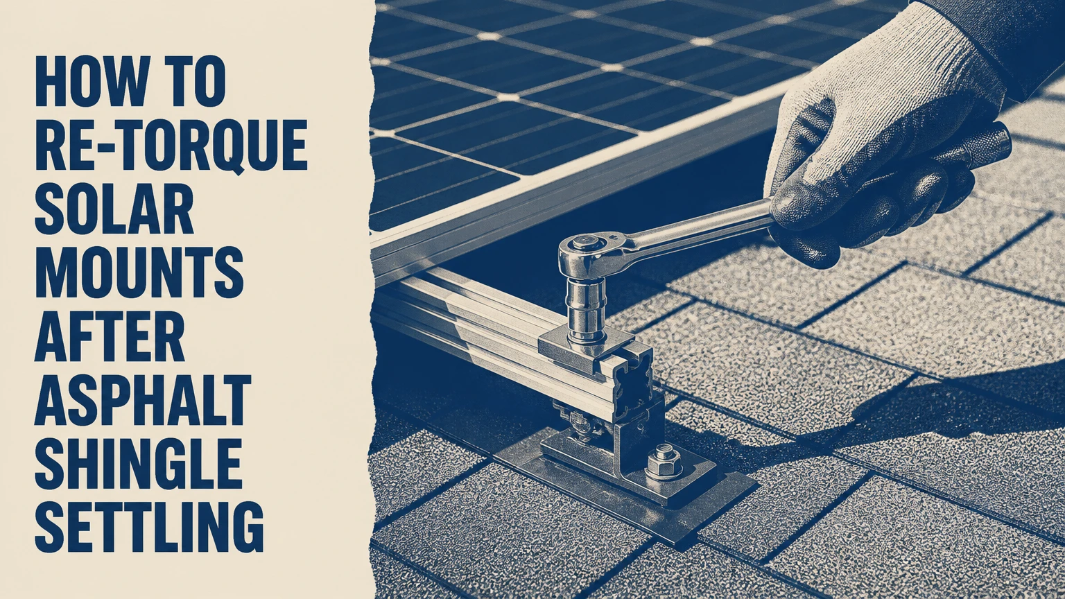
Solar mount re-torquing means inspecting each accessible racking connection, verifying the manufacturer’s specified torque, and correcting confirmed under-tightening without damaging the roof or array. Asphalt shingle settling can change joint compression, but visual evidence, fastener condition, installation documents, and the racking manual must determine whether retorquing is appropriate.
Key Facts at a Glance
A universal solar-mount torque value does not exist; the racking manufacturer and fastener type control the specification.
A torque wrench measures turning resistance, not lag-screw pullout strength or rafter integrity.
Solar shutdown does not remove all rooftop DC electrical hazards, because illuminated modules can still produce voltage.
Retorquing cannot repair a stripped rafter, a missed structural member, cracked flashing, or a roof leak.
A spinning lag, damaged flashing, displaced EPDM washer, or crushed shingle requires investigation before tightening.
A calibrated hand torque wrench is appropriate; an impact driver is not a substitute for final torque verification.
Should Asphalt Shingle Settling Trigger Retorquing?
Asphalt shingle settling should trigger an inspection, not an automatic tightening campaign. New shingles can compress under flashing and mounting hardware, while temperature changes, wind vibration, installation error, and roof-deck movement can alter joint preload; however, the amount of movement varies substantially by shingle design, roof temperature, underlayment, mount geometry, and fastener placement.
The common “two summers” or “35 to 50 percent torque loss” figures are not universal engineering values. Asphalt shingles are roofing products, not calibrated structural compression pads, and a published product specification rarely establishes a predictable torque-loss rate beneath a solar attachment. Treat those numbers as unsupported unless an engineer or the racking manufacturer supplies a project-specific basis.
The correct service objective is to restore the designed joint condition. That may mean leaving a correctly torqued fastener alone, replacing a damaged washer, repairing flashing, reinforcing a failed wood connection, or removing and reinstalling a mount.
What changes inside the attachment joint?
A lag screw creates clamping force by stretching slightly as it is tightened. If a soft layer compresses, the fastener can lose some stretch and therefore some preload. Thermal movement between aluminum rails, stainless steel hardware, steel flashing, wood, and asphalt roofing can add cyclic movement.
Torque is an indirect measurement because friction consumes much of the wrench input. Thread lubricant, corrosion, galling, dirt, washer condition, and the contact surface can produce different clamp loads at the same torque. That is why a higher reading does not automatically mean a stronger attachment.
IronRidge’s installation documentation, for example, specifies torque by connection and hardware rather than by a universal roof-wide number. Unirac, SnapNrack, QuickBOLT, and other manufacturers likewise publish system-specific instructions.
Before You Start: Time, Tools, and Stop Conditions
A small, accessible array typically requires 2-4 hours for inspection and documentation, excluding repairs. A 5-10 kW residential array commonly requires 4-8 labor hours when technicians must identify every attachment, access multiple roof planes, and record results. These are typical service-planning ranges, not guaranteed production times.
| Requirement | Typical specification | Why it matters | Stop condition |
|---|---|---|---|
| Torque wrench | 3/8-inch drive, target within middle 20-80% of range | Improves measurement control | No documented calibration or damaged mechanism |
| Socket set | Manufacturer-specified SAE or metric sockets | Prevents rounded heads | Wrong size or corroded fastener |
| Roof access | Dry surface, moderate temperature, stable footing | Reduces shingle and fall damage | Rain, frost, high wind, or brittle hot shingles |
| Safety equipment | Full-body harness, rated anchor, lifeline, edge protection as required | Controls fall exposure | No compliant anchor or rescue plan |
| Inspection materials | Camera, flashlight, plastic probe, notebook, paint marker | Creates a service record | Cannot identify each attachment |
| Electrical controls | AC disconnect, inverter procedure, DC and rapid-shutdown instructions | Reduces electrical exposure | Shutdown status cannot be verified |
| Replacement parts | Exact washers, bolts, flashing, and approved sealant | Maintains system design | No matching manufacturer parts |
OSHA 29 CFR 1926.501(b)(1) states, “The employer shall ensure that each employee on a walking-working surface with an unprotected side or edge that is 6 feet (1.8 m) or more above a lower level is protected from falling.” A homeowner working alone should treat the rescue plan as a prerequisite, not an optional accessory.
Do not climb onto the roof when shingles are wet, icy, unusually hot, visibly brittle, or covered with algae. Do not step on modules, lean tools against glass, walk on unsupported rail, or place a ladder against the array.
How to Re-Torque Solar Mounts After Asphalt Shingle Settling
The following process applies only when the racking manual, roof condition, and electrical safety plan permit service. The racking manufacturer’s instructions override the sequence and values below.
Step 1: Identify the racking system and attachment type
Find the installation invoice, permit packet, racking labels, rail profile, clamp design, and fastener dimensions before touching hardware. Photograph the array from the ground, then create a mount map that labels each attachment by row and column.
Common categories include flashed lag attachments into rafters, structural screws into approved decking, rail-less module attachments, and clamps connecting modules to aluminum rail. The same-looking stainless bolt can have a different torque value in a rail splice, mid-clamp, end-clamp, or roof attachment.
Success checkpoint: Every connection has an identified manufacturer, part family, fastener size, and manual reference.
Common mistake: Using a torque chart from a visually similar system.
Step 2: Establish electrical and fall protection controls
Follow the inverter manufacturer’s shutdown procedure, open the required AC disconnect, use the system’s DC disconnect where provided, and confirm rapid-shutdown behavior according to the equipment instructions. SolarEdge explains that module-level power electronics and rapid shutdown are system-dependent, so a generic “turn off the inverter” instruction cannot establish zero voltage at every conductor.
Illuminated photovoltaic modules can still generate DC voltage. Never disconnect module connectors, cut conductors, move wiring, or place a conductive tool across energized terminals during mechanical service. A qualified solar electrician should handle any wiring found pinched, abraded, unsupported, or close to a fastener.
Success checkpoint: The shutdown state is recorded, conductors are visually protected, and a qualified person controls electrical testing.
Common mistake: Assuming an AC disconnect makes rooftop DC wiring safe to handle.
Step 3: Inspect the array before loosening anything
Look for bowed rails, module-frame gaps, shifted clamps, cracked glass, frame distortion, exposed wires, uplifted shingles, staining, displaced flashing, and fasteners that sit visibly high or low. Inspect the roof from the attic when possible; water trails and crushed decking can reveal defects that are invisible from above.
Do not use a feeler gauge to declare a mount structurally sound. A gap may indicate compressed roofing, a missing washer, a bent bracket, a loose connection, or an incorrectly installed mount. Record the condition with a photograph and measurement before applying force.
| Observation | Likely significance | Immediate action | Retorque status |
|---|---|---|---|
| Paint mark remains aligned | No visible fastener rotation | Measure and record condition | Verify only |
| Clamp visibly lifted | Loss of contact or wrong hardware | Isolate module and inspect | Do not tighten blindly |
| Shingle cracked or extruding asphalt | Roofing damage or excessive compression | Call roofing professional | Repair first |
| Lag head turns with wood dust | Possible stripped connection | Remove only under repair plan | Do not continue |
| Wire insulation damaged | Electrical and fire hazard | De-energize and repair | Stop mechanical work |
| Flashing edge exposed | Waterproofing defect | Follow flashing manual | Sealant is not the first fix |
Success checkpoint: Each defect is classified before a wrench is used.
Common mistake: Tightening the most visibly loose point and assuming the array is corrected.
Step 4: Clean only the hardware contact area
Remove leaves and loose nesting material with a soft plastic or nylon brush. Keep debris from falling beneath flashing or into wire-management clips. Do not scrape anodized rail surfaces with a wire brush, knife, or screwdriver.
Never lift shingles, pry flashing, pull sealant, or move module wiring merely to make a connection easier to reach. Those actions convert a torque check into roof and electrical work.
Success checkpoint: The socket fully seats on clean hardware without disturbing roofing components.
Common mistake: Cleaning aggressively enough to remove protective coatings or granules.
Step 5: Set the exact manufacturer torque
Locate the current installation manual for the exact racking family and hardware. Confirm whether the value is inch-pounds or foot-pounds, whether it applies dry or lubricated threads, and whether the specification is for final tightening, initial installation, or a replacement part.
Convert units carefully: 12 foot-pounds equals 144 inch-pounds. Do not infer that a 1/4-inch lag, M8 bolt, and rail clamp share a value. The manufacturer may specify a range, a single target, a sequence, or a special washer arrangement.
| Connection example | Typical published style | Why a generic number fails | Required verification |
|---|---|---|---|
| Roof attachment lag | System-specific foot-pound value | Rafter and washer design vary | Lag diameter, washer, mount model |
| Rail bolt | Inch-pound or foot-pound value | Aluminum channel can deform | Nut, channel, and bolt grade |
| Mid-clamp | Often inch-pound value | Clamp geometry changes pressure | Clamp model and module frame |
| End-clamp | Often separate from mid-clamp | Edge loading differs | End position and frame height |
| Rail splice | Manufacturer-specific value | Splice plates carry rail movement | Splice location and hardware |
| Deck screw | Engineering-approved value only | Deck thickness and substrate vary | Structural drawing or manual |
A torque wrench should be calibrated according to the owner’s quality system and manufacturer instructions. ANSI/ASME B107.10 establishes requirements for torque instruments, but compliance with a standard does not make an unknown wrench accurate at every setting. Store a click wrench at its prescribed minimum setting, and do not use it after a fall or visible damage until it is checked.
Success checkpoint: The service record names the manual revision, fastener, units, target, and wrench identification.
Common mistake: Confusing 15 inch-pounds with 15 foot-pounds, a twelvefold error.
Step 6: Verify torque without forcing the fastener
Place the socket squarely on the head or nut. Apply smooth, controlled pressure in the tightening direction until the wrench indicates the specified value. If the fastener moves substantially before reaching the target, record the movement and investigate the joint rather than repeatedly cycling the wrench.
A click does not prove that the wood has adequate threads, that the lag reaches a rafter, or that flashing is correctly installed. If a lag turns continuously, rises from the roof, or reaches the target with abnormal movement, stop and escalate.
Do not back every fastener off before retightening. Breaking a stable joint can disturb flashing, crush shingles, or create a new leak. The normal field approach is to verify first, then adjust only the connection permitted by the manufacturer’s procedure.
Success checkpoint: The connection reaches the specified value without abnormal rotation, crushing, cracking, or movement.
Common mistake: Using an impact driver because the torque wrench cannot reach the fastener.
Step 7: Follow the documented sequence
Use the racking manufacturer’s sequence. If no sequence exists, obtain written technical guidance before servicing a large array. A blanket “inside-out” rule is not universal; some systems specify clamp order, module order, rail splice order, or staged tightening.
Work in a controlled row-by-row pattern and mark each completed connection on the mount map. Keep one person recording values while another operates the wrench when the roof layout is complex.
Success checkpoint: No attachment is skipped, duplicated, or tightened against an unidentified defect.
Common mistake: Tightening random points until the rails appear visually straight.
Step 8: Replace damaged hardware and correct defects
Replace cracked EPDM washers, deformed clamps, corroded fasteners, damaged flashing, and missing bonding hardware with approved parts. Stainless steel galling can occur when compatible threaded components are turned rapidly under load; do not force a seized connection with an impact tool.
Sealant is not a structural repair. Use only the product and location specified by the racking or roofing manufacturer. Adding a bead around every bracket can trap water, hide a flashing defect, interfere with drainage, and complicate later replacement.
Success checkpoint: The repair restores the designed hardware stack and flashing path, not merely a tighter bolt.
Common mistake: Applying roofing cement around a mount instead of repairing a displaced flashing component.
Step 9: Mark, photograph, and report the service
Apply a small torque seal mark only where the manufacturer or service policy permits it, and place the mark across the fastener and adjacent stationary surface. Photograph each repaired defect, not merely the completed array.
The report should include array address, weather, roof condition, racking brand and model, manual revision, fastener identification, target torque, measured or adjusted result, defects, replacement parts, electrical shutdown procedure, and technician name.
Success checkpoint: Another qualified technician can reconstruct what was checked without returning to the roof.
Common mistake: Recording “all bolts tightened” without mount locations or values.
How Do Mount Types Change the Service Method?
Flashed rafter mounts, direct-to-deck attachments, and rail-less systems require different inspections and torque instructions. The roof attachment, not the module wattage, determines the structural question.
| Mount type | Primary load path | Main settling concern | Service emphasis |
|---|---|---|---|
| Flashed L-foot | Lag into rafter, flashing, L-foot, rail | Compression or flashing displacement | Verify rafter engagement and flashing |
| Direct-to-deck | Approved structural screws into deck | Deck thickness and withdrawal capacity | Confirm engineering approval and substrate |
| Rail-less attachment | Individual roof attachments and module clamps | Localized module-frame loading | Check every attachment and alignment |
| Rail splice and clamp | Aluminum rail and stainless hardware | Thermal movement and friction changes | Use exact clamp and splice values |
| Tile or specialty roof | Custom flashing and roof interface | Waterproofing movement | Use installer or roofing specialist |
The AI Overview’s sample torque ranges should not be copied into a work order. A value such as 13-15 foot-pounds may be correct for one lag and wrong for another, while a rail clamp commonly uses an entirely different inch-pound value. Exact numbers belong to the named installation manual.
What Are Typical Time and Costs?
Typical residential solar mount inspection and torque service costs range from $350-$1,200 for a small or medium array, while extensive repairs, module removal, roof access difficulties, and engineering review can raise the total above $2,000. Labor varies by region and usually reflects mobilization, fall protection, documentation, and repair risk more than wrench time.
| Service scope | Array example | Typical labor time | Typical price range |
|---|---|---|---|
| Inspection only | 5-15 modules | 1.5-3 hours | $250-$500 |
| Verify and adjust | 12-25 modules | 3-6 hours | $450-$900 |
| Large array service | 30-60 modules | 6-12 hours | $800-$1,600 |
| Roof attachment repair | Any size | 4-16 hours | $700-$2,500+ |
| Engineering assessment | Complex commercial roof | 1-3 site visits | $1,000-$4,000+ |
These figures are typical planning ranges, not published national prices. Ask whether the quote includes roof repairs, module removal, electrical labor, replacement hardware, permit requirements, and a written torque report.
How Often Should Solar Mounts Be Checked?
A new array deserves a documented inspection after the first major seasonal cycle, then periodic checks based on the roof, climate, warranty, and manufacturer instructions. Routine inspection is more defensible than a universal three-year or five-year retorque interval because a correctly torqued joint should not be loosened without a reason.
| Situation | Initial check | Later interval | Escalation trigger |
|---|---|---|---|
| New asphalt roof | 6-18 months | Every 2-3 years | Shingle crushing or movement |
| Older brittle shingles | Before installation | Annual roof inspection | Granule loss or cracking |
| High-wind coastal site | 6-12 months | Annual | Wind event or uplift evidence |
| Snow and ice region | After first winter | Annual | Snow damage or rail deformation |
| Commercial array | Per O&M plan | Annual or semiannual | Insurance or engineer requirement |
| Off-grid owner-maintained system | 12 months | Every 2-3 years | Any irregular torque result |
Roof inspections after hail, hurricanes, tornadoes, major snow loading, or tree impact should precede torque work. A bent rail or shifted module can indicate a larger load-path failure.
What If a Lag Spins, Seizes, or Will Not Tighten?
A lag that spins indefinitely indicates a possible stripped wood connection, a missed rafter, a broken fastener, or a hole larger than the screw’s effective threads. The correct response is to stop, document the location, remove the mount only under a repair plan, and verify the structural substrate with the installer, roofer, or engineer.
Do not inject generic epoxy, wood filler, or outdoor sealant into a structural lag hole and assume the connection is restored. Structural repair may require a new attachment location, an engineered helical or through-bolt solution, rafter reinforcement, or replacement of damaged decking. The repair must preserve flashing and edge distances.
A seized stainless fastener can gall when turned aggressively. Use the manufacturer-approved lubricant only if the manual permits it, and replace contaminated or damaged hardware rather than improvising a lubricant that changes the torque relationship.
Which defects require a roofer?
A roofer should evaluate torn or cracked shingles, exposed nail heads, displaced flashing, water staining, damaged underlayment, granule loss around an attachment, and asphalt extrusion. A solar technician can identify racking defects, but a torque adjustment cannot restore a failed water-shedding layer.
A leak below an attachment may originate upslope, at a vent, along a valley, or at a flashing seam. Do not assume the nearest mount caused it. Water follows roof-deck paths.
Should a Homeowner Retorque Solar Mounts?
Most grid-tied homeowners should hire the original installer or a solar service contractor for roof-mounted retorquing. DIY work is reasonable only for an experienced person with compliant fall protection, the exact racking manual, a suitable calibrated wrench, electrical competence, and a safe rescue plan.
| User situation | Best service choice | Main reason | DIY suitability |
|---|---|---|---|
| Array under workmanship warranty | Original installer | Preserves records and warranty path | Low |
| Out-of-warranty residential array | Independent solar technician | Combines racking and electrical knowledge | Low to moderate |
| Active roof leak | Roofing contractor plus solar technician | Separates water and electrical repairs | Low |
| Off-grid ground or low-slope array | Experienced owner | Easier access and reduced fall exposure | Moderate |
| Commercial rooftop system | O&M provider and engineer as needed | Requires reports and asset controls | Very low |
The original installer may have proprietary torque records, replacement hardware, and warranty obligations. If the installer is unavailable, choose a contractor that names the racking manufacturer on the proposal and agrees to provide connection-level documentation.
Common Mistakes and How to Fix Them
- Using a generic torque table: Stop and obtain the exact manual. Hardware diameter alone does not identify the required preload.
- Retorquing a leaking attachment: Repair the flashing and roof layers first. Tightening can worsen crushed shingles.
- Applying sealant around every mount: Remove unnecessary sealant only under the approved repair method, then restore the specified flashing system.
- Treating a click as proof of strength: Investigate substrate engagement, wood condition, and mount location separately.
- Testing every fastener after a storm without inspection: Photograph rail and module movement first, because torque cannot correct bent metal or failed attachments.
- Handling conductors after inverter shutdown: Keep hands and tools away from DC connectors unless a qualified person verifies the electrical condition under the equipment procedure.
A practitioner rule of thumb is to stop whenever the fastener behavior changes from predictable resistance to free spinning, sudden binding, or visible roof movement. Abnormal behavior contains more diagnostic information than the final torque reading.
What Should the Service Record Contain?
A defensible service record connects each physical attachment to a result. Use a roof plan, row-column labels, photographs, and a defect code rather than a single statement that the array was “checked.”
| Record field | Example value | Reason |
|---|---|---|
| Racking | IronRidge XR10, manual revision 2.3 | Identifies design basis |
| Location | Array A, row 2, mount 4 | Makes result traceable |
| Fastener | 5/16-inch lag, stainless washer | Prevents hardware ambiguity |
| Torque target | 144 inch-pounds | Records units and value |
| Result | Verified, adjusted, or failed | Separates observation from repair |
| Roof condition | 2022 architectural shingle, dry | Adds substrate context |
| Defect photo | IMG_2041 | Links evidence to location |
| Replacement | EPDM washer, manufacturer part number | Supports future maintenance |
| Technician | Name and certification | Establishes responsibility |
Do not claim that every connection was “within tolerance” if the technician sampled only a few points. State the sample size and selection method. For commercial systems, follow the owner’s operations and maintenance plan, insurer requirements, and engineer instructions.
FAQ
Can solar mounts loosen without visible shingle settling?
Yes. Wind vibration, thermal cycling, incorrect initial torque, thread galling, missing washers, rail movement, and substrate failure can reduce joint performance without obvious shingle compression. A visual inspection can identify warning signs, but only the manufacturer’s service procedure and a structural evaluation can determine the appropriate correction.
Can I use a regular socket wrench for solar mount retorquing?
A regular socket wrench can remove or initially position hardware, but it cannot verify a specified torque. Final adjustment requires a suitable calibrated torque wrench with the correct socket and measurement units. An impact driver can damage stainless hardware, aluminum channels, module frames, and wood connections.
Does retorquing fix a solar-panel roof leak?
Retorquing does not by itself fix a roof leak. Leaks may involve flashing, underlayment, shingles, roof valleys, vents, or damaged decking, and overtightening can worsen the roof interface. A roofer or qualified solar contractor should identify the water path before any fastener is loosened.
How can I find my solar racking torque specifications?
Search the installation packet, permit documents, installer records, rail labels, and manufacturer technical library using the racking model and hardware part number. Confirm the manual revision and units. If the model cannot be identified, do not substitute a value from another brand or from a generic online table.
Is asphalt shingle settling normal under solar panels?
Some compression and weathering are normal, especially where flashing and roofing layers experience repeated heat cycles. Excessive crushing, exposed fasteners, asphalt extrusion, cracked shingles, or a mount that moves under light hand pressure are not conditions to normalize. Those signs require inspection of the roof and attachment.
Should mounts be retorqued after a hurricane or hailstorm?
A severe-weather inspection should come first. Look for shifted modules, bent rails, cracked glass, torn shingles, exposed wiring, and flashing displacement before testing torque. A storm-damaged array may require module removal, structural review, electrical testing, or roof repair rather than simple fastener adjustment.
The Bottom Line
How to Re-Torque Solar Mounts After Asphalt Shingle Settling is a manufacturer-specific inspection and repair process, not a universal tightening exercise. Identify the racking system, control fall and electrical hazards, inspect the roof and load path, verify the published torque, stop at abnormal fastener behavior, and document every result. When the roof, rafter, flashing, or wiring is defective, repair that underlying condition instead of forcing a tighter connection.