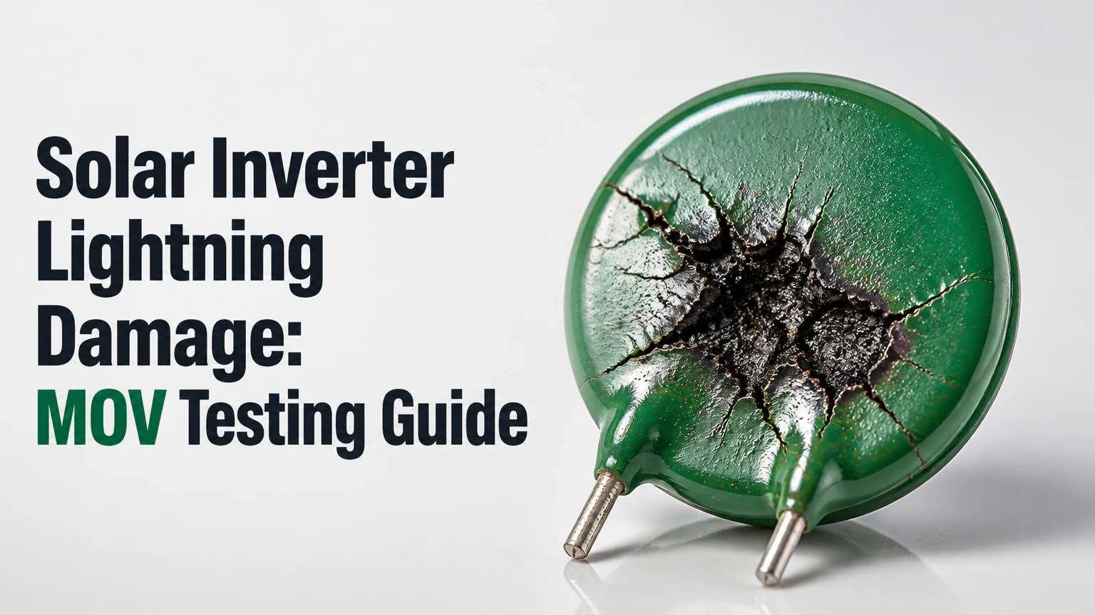
A metal oxide varistor, or MOV, is a sacrificial voltage-limiting component that diverts transient energy away from solar inverter electronics. After lightning or a severe switching surge, test the MOV only after complete isolation, beginning with visual inspection and an isolated high-resistance measurement; an open-circuit DMM result indicates no obvious short, but it cannot prove full surge capability.
Key facts at a glance
An MOV normally has very high resistance and conducts heavily only when transient voltage rises above its protective region.
A removable SPD cartridge with a red indicator generally requires replacement, not bench testing.
A DMM resistance test can identify a shorted or badly leaky MOV, but an OL reading does not verify its clamping voltage or impulse-current rating.
PV SPDs require a photovoltaic DC rating, commonly identified as (U_{CPV}), that exceeds the maximum calculated open-circuit string voltage at the installation’s lowest temperature.
IEC Type 1 and Type 2 describe tested surge duties and installation roles, not a universal guarantee against direct lightning damage.
Internal inverter work can expose lethal AC, PV DC, and stored capacitor energy; qualified personnel should follow the inverter manufacturer’s service procedure.
What Is an MOV in a Solar Inverter?
A solar inverter MOV is a voltage-dependent resistor connected across a protected circuit, where it remains nearly nonconductive during normal operation and becomes conductive during a short-duration overvoltage. Zinc-oxide grain boundaries create the nonlinear behavior that lets an MOV clamp a surge without dissipating continuous operating power.
MOV protection is not the same as a fuse. A fuse interrupts sustained overcurrent, while an MOV diverts transient current and absorbs a finite amount of energy. Repeated surges, excessive temporary overvoltage, heat, or a surge beyond the device rating can damage the zinc-oxide structure and increase leakage.
The MOV may be installed as a discrete disc on a printed circuit board or inside a replaceable surge protective device. A complete SPD commonly adds a thermal disconnector, status indicator, backup overcurrent protection, and sometimes a remote alarm contact. IEC 61643-11 covers low-voltage AC surge protective devices, while IEC 61643-31 addresses SPDs connected to the DC side of photovoltaic systems.
How does an MOV divert lightning energy?
An MOV reduces the voltage presented to downstream electronics by providing a lower-impedance path when a transient appears. The path may be line-to-line, positive-to-negative, line-to-neutral, or line-to-protective-earth, depending on the inverter schematic and SPD topology.
A lightning event does not need to strike the panels directly. A nearby strike can induce a high-voltage pulse in long PV conductors, and a utility-side event can enter through the AC supply. The effectiveness of an MOV depends on the entire installation: bonding, conductor routing, SPD location, lead length, grounding impedance, and coordination between upstream and downstream SPDs.
A short SPD connection is important because every metre of conductor adds inductive voltage during a fast surge. The MOV can clamp correctly at its terminals while the inverter sees a substantially higher voltage at the end of long, poorly routed leads.
Where Are MOVs Installed?
Solar inverter surge protection can appear in several circuits, and inspecting only one location can miss the damaged device. The service manual and wiring diagram identify whether the inverter has protection on the PV input, AC output, battery terminals, communications ports, or each separate string input.
| Protection location | Typical device | Main transient path | Typical service clue |
|---|---|---|---|
| PV positive to negative | DC MOV or PV SPD | Differential-mode PV surge | PV insulation or input fault |
| PV conductors to PE | PV SPD or MOV array | Common-mode surge to bonding system | SPD flag changes or ground fault |
| AC line to neutral | AC MOV | Utility switching or lightning surge | Inverter will not boot or output trips |
| AC line and neutral to PE | AC SPD | Common-mode mains surge | RCD, breaker, or earth fault indication |
| RS-485 or Ethernet | TVS diode, GDT, or dedicated protector | Induced communications surge | Lost monitoring or damaged port |
| Battery positive and negative | DC SPD or MOV network | Battery-cable transient | Battery communication or DC bus fault |
What specifications determine whether an MOV is suitable?
The replacement must match the original circuit design, not merely the disc diameter or printed voltage. The most important values are continuous operating voltage, varistor voltage, protective level, surge current, energy, temporary overvoltage withstand, polarity, physical spacing, and agency approvals.
| Specification | Meaning | Selection rule | Common error |
|---|---|---|---|
| (V_{MCOV}) or (U_c) | Maximum continuous RMS AC or DC voltage | Exceed the circuit’s highest normal steady voltage | Choosing nominal voltage only |
| (V_{1mA}) | Varistor voltage at 1 mA test current | Compare with the approved original part | Treating it as the clamp voltage |
| (U_p) or (V_p) | Maximum measured protective level under a specified impulse | Must protect the inverter’s insulation and electronics | Comparing values from different test currents |
| (I_n) | Nominal discharge current, usually an 8/20 μs test | Use the SPD design and installation exposure | Substituting Imax for routine test duty |
| (I_{max}) | Maximum discharge current under the manufacturer’s test | Do not assume repeated survival at this value | Calling it a continuous-current rating |
| (U_{CPV}) | PV SPD maximum continuous DC operating voltage | Exceed maximum cold-weather string (V_{oc}) | Selecting from 400 V nominal string voltage |
| (I_{scpv}) | Short-circuit current interrupt rating for PV SPD backup protection | Meet the available PV fault current | Ignoring DC arc interruption |
For PV arrays, calculate the cold-weather maximum string open-circuit voltage before choosing (U_{CPV}). A nominal “400 V string” can exceed that value significantly at low temperature, so a 500 V or 600 V choice cannot be made safely from nominal voltage alone.
An MOV with too-low MCOV can conduct during normal operation or during a temporary overvoltage and overheat. An MOV with excessive protective voltage may survive longer while allowing a damaging voltage to reach the inverter. Replacement selection therefore requires the original part number, schematic position, and manufacturer-approved equivalent.
How Do You Test a Solar Inverter MOV Safely?
A qualified technician should isolate every energy source, verify absence of voltage with an appropriately rated tester, and follow the inverter’s discharge and access instructions before testing. The work normally takes 15-30 minutes for an accessible modular SPD, while PCB removal and component replacement can take 45-90 minutes or longer.
Before testing
| Item | Typical requirement | Why it matters |
|---|---|---|
| AC supply | Open breaker and verify absence of voltage | Grid terminals can remain lethal |
| PV input | Open DC isolator and isolate every string | PV modules generate voltage in daylight |
| Battery | Open battery disconnect where fitted | Batteries can deliver high fault current |
| Stored energy | Wait the manufacturer-specified period | Capacitors may retain hazardous charge |
| Test instrument | CAT III or CAT IV meter with suitable voltage rating | Prevents an instrument category failure |
| Replacement record | Photograph labels and wiring | Prevents wrong-polarity or wrong-rating installation |
Five to ten minutes is only a common waiting interval, not proof of safety. Some inverters specify longer discharge times, and a meter must verify zero or safe voltage between each relevant terminal pair before contact. Never rely on a front-panel display, an open isolator alone, or a single measurement to establish isolation.
Step 1: Identify the protection circuit
Read the inverter label, service manual, and SPD marking before touching a component. Record whether the device protects PV positive-to-negative, each pole-to-earth, AC line-to-neutral, or another path.
You will know this step is complete when the device’s part number and circuit position are documented. A common mistake is to replace a visually similar AC MOV in a PV DC position, which can cause immediate failure or sustained heating.
Step 2: Inspect the SPD and surrounding board
Look for a red status window, tripped thermal indicator, cracked housing, soot, melted plastic, lifted PCB tracks, carbonized laminate, swollen capacitors, damaged terminal blocks, and discolored cable insulation. Smell can reveal overheated epoxy, but do not use smell as a substitute for electrical inspection.
A failed plug-in cartridge should normally be replaced as a complete manufacturer-approved cartridge. Do not assume that changing only its internal MOV restores thermal disconnection or backup protection.
Lightning damage often travels beyond the arrester. Inspect bridge rectifiers, input fuses, MOSFETs or IGBTs, gate-drive components, control power supplies, communication interfaces, and current-sense circuits before re-energizing the inverter.
Step 3: Isolate the MOV from parallel circuitry
Remove the plug-in SPD cartridge from its base, or disconnect at least one lead of a discrete MOV according to the service procedure. Desoldering a board-mounted MOV requires ESD precautions, controlled heat, and documentation of polarity and lead routing.
An in-circuit resistance reading is not diagnostic because capacitors, transformer windings, bleeder resistors, rectifiers, filters, and other MOVs can create parallel paths. The isolated component, not the connected inverter assembly, is the object under test.
Step 4: Measure resistance with a DMM
Set a quality DMM to its highest resistance range and measure across the isolated MOV. Reverse the probes and repeat the measurement, although an MOV is bidirectional and should show the same broad result in both polarities.
| Isolated DMM result | Probable interpretation | Required action |
|---|---|---|
| OL in both directions | No obvious low-resistance failure | Continue system inspection; do not certify surge health |
| Stable resistance under 1 kΩ | Shorted or severely failed MOV | Replace the approved MOV or complete SPD |
| Tens of kΩ to several MΩ | Leakage, contamination, or degraded MOV | Compare with data sheet and replace if outside specification |
| Reading changes while charging | Meter interaction with capacitance or circuit residue | Clean, isolate, and retest |
| Different readings by probe direction | Wiring or parallel path remains | Recheck isolation |
| Unstable low reading | Moisture, carbon tracking, or thermal damage | Replace and inspect the board |
The AI Overview threshold of 100 MΩ is not a universal pass-fail standard. MOV leakage varies with device size, temperature, applied voltage, contamination, and the manufacturer’s specified test method; many healthy devices will read beyond the meter range, but the data sheet governs acceptance.
A DMM cannot reproduce an 8/20 μs or 10/350 μs lightning-current waveform. An OL reading means the MOV is not shorted at the meter’s low test voltage. It does not prove that the MOV still has the correct (V_{1mA}), (U_p), energy capability, or impulse-current performance.
Step 5: Decide whether insulation testing is permitted
Do not connect a megohmmeter directly to an MOV, inverter input, or complete SPD unless the manufacturer explicitly specifies the test voltage and connection. A megohmmeter can exceed the MOV’s conduction region, trigger its protective action, stress adjacent semiconductor devices, and produce a misleading result.
Insulation resistance testing is appropriate for some isolated cables and assemblies, not automatically for the surge arrester itself. If a manufacturer permits testing an isolated MOV, use the exact data-sheet procedure, test voltage, duration, and acceptance limit. Otherwise, replace a suspect SPD and test the wiring separately.
This is an important correction to generic advice that recommends a 250 V or 500 V Megger for every MOV. A test voltage below the nominal system voltage can still be above the particular MOV’s conduction region, while an inverter’s connected electronics may be damaged long before the meter displays a useful reading.
Type 1, Type 2, or Onboard MOV?
Type 1 and Type 2 labels describe surge protective device test duties and installation roles, while onboard MOVs describe a physical integration method. A modular Type 2 PV SPD is usually easier to service than a soldered MOV, but Type 2 protection is not equivalent to protection from every direct lightning current.
| Option | Test-wave association | Installation role | Service consequence |
|---|---|---|---|
| Type 1 SPD | 10/350 μs current impulse | Higher lightning-current exposure | Larger device and coordinated backup required |
| Type 2 SPD | 8/20 μs current impulse | Induced and switching surges | Common at PV combiner or inverter input |
| Type 1+2 SPD | Both declared test duties | Combined upstream exposure | Verify both PV rating and backup protection |
| Onboard MOV | Manufacturer-specific component test | Local inverter PCB protection | Board-level repair and warranty risk |
The 10/350 μs and 8/20 μs waveforms are not interchangeable. Their peak current, duration, and energy differ, so a device’s kA value must be read with its waveform and test category. IEC 61643-31 provides PV-specific requirements; local installation rules and the equipment manufacturer determine the final arrangement.
Is an external SPD better than an onboard MOV?
An external SPD usually improves serviceability and can reduce surge energy entering the inverter when installed at the correct boundary with short conductors. An onboard MOV remains valuable because residual voltage can appear inside the inverter, particularly when cable spacing, bonding, or upstream coordination is imperfect.
External protection is not automatically better. A remote combiner box with long conductors can leave a high inductive voltage at the inverter, and an incorrectly rated DC SPD can fail under normal PV voltage. The practical rule is coordinated protection at the array or combiner and inverter interfaces, with conductor routing kept short and direct.
What Should You Do After Lightning Damage?
After a storm, replace a red-indicator SPD, isolate a shorted MOV, and do not repeatedly restart an inverter that reports ground fault, isolation fault, insulation fault, or DC bus failure. A lightning event can damage semiconductors without leaving a visible mark, so successful boot-up does not establish safe insulation or reliable conversion.
| Symptom after storm | Likely areas | Safe next decision |
|---|---|---|
| SPD indicator red | Thermal disconnector operated | Replace matching cartridge and inspect cause |
| Inverter dead, AC breaker trips | AC SPD, rectifier, switching stage | Keep isolated; perform qualified component diagnosis |
| Isolation fault with normal-looking board | PV cable, connector, SPD leakage, moisture | Test strings and wiring separately |
| PV input absent on one tracker | Input fuse, connector, MOV, tracker stage | Compare tracker voltages and inspect each path |
| Communications lost only | RS-485, Ethernet, control board | Test external network equipment and port isolation |
| Repeated SPD failure | Temporary overvoltage, poor bonding, wrong MCOV | Investigate system voltage and installation geometry |
Why can an MOV fail without looking burned?
An MOV can suffer electrical degradation before its disc cracks or its housing darkens. Small surges and temporary overvoltages alter leakage and thermal behavior, while moisture, contamination, and repeated heating can reduce remaining energy margin.
A low resistance is a strong failure indication. A normal-looking body and OL reading are weaker evidence. If the event was severe, the inverter still reports a fault, or nearby components show damage, treat the MOV as one part of a wider failure investigation rather than declaring the inverter healthy.
Common Testing and Replacement Mistakes
The most expensive errors occur after the first failed measurement, when a technician restores power before identifying the event’s cause. These failure modes deserve separate checks.
- Testing in circuit: Parallel components produce false resistance readings. Isolate one lead or remove the cartridge.
- Using nominal PV voltage: Select (U_{CPV}) from maximum cold-weather (V_{oc}), not the label “400 V string.”
- Installing a lower-rated MOV: A lower MCOV can conduct during normal operation and overheat.
- Using a Megger indiscriminately: Test only wiring or components permitted by the manufacturer.
- Replacing only the disc in a modular SPD: The thermal disconnect and indicator may also be compromised.
- Ignoring lead length: Long loops add inductive voltage and reduce effective protection.
- Restarting after a ground fault: A damaged rectifier or insulation path can turn a transient fault into fire or shock risk.
A practitioner rule of thumb is to photograph every terminal and conductor before removal, record the original part number, and compare the replacement’s (U_{CPV}), (U_c), (U_p), discharge ratings, and backup-fuse requirements line by line. Disc diameter alone is not a specification.
How Much Does MOV or SPD Repair Cost?
Typical service pricing is about $20-$60 for a modular Type 2 cartridge, $1-$5 for a discrete MOV, and $150-$350 for professional diagnostic labor. A cartridge swap may take 5-15 minutes after isolation, while PCB access, soldering, and secondary damage testing commonly take 45-90 minutes.
| Repair scenario | Typical parts cost | Typical labor time | Main uncertainty |
|---|---|---|---|
| Plug-in AC SPD cartridge | $20-$60 | 5-15 minutes | Brand and rating |
| Plug-in PV DC SPD cartridge | $30-$100 | 10-20 minutes | (U_{CPV}), poles, backup fuse |
| Soldered MOV replacement | $1-$5 per MOV | 45-90 minutes | PCB access and thermal damage |
| Damaged inverter power board | $300-$1,500 or more | 1-4 hours | Model availability and warranty |
| Full inverter replacement | $800-$3,000 or more | 2-6 hours | Capacity, permitting, commissioning |
These are typical field ranges, not fixed prices. Roof access, travel, manufacturer authorization, high-voltage testing, replacement-board availability, and local labor rates can change the total substantially.
Which Test Result Means Replace Versus Investigate?
Replace the SPD when its mechanical indicator has operated, its isolated resistance is abnormally low, its housing is cracked or thermally damaged, or the manufacturer specifies replacement after a known surge. Investigate the complete inverter when the MOV passes a basic resistance test but the inverter has persistent insulation, boot, DC bus, tracker, or communication faults.
The correct sequence is:
- Keep AC, PV, and battery sources isolated.
- Photograph the installation and record fault codes.
- Inspect every SPD and protected terminal.
- Test PV strings, AC wiring, and protective bonding independently.
- Remove or isolate suspect MOVs and perform the permitted DMM test.
- Replace the complete approved SPD or exact component equivalent.
- Check fuses, rectifiers, switching devices, connectors, and PCB tracks.
- Perform manufacturer-required insulation, polarity, functional, and commissioning tests.
- Re-energize in the specified order and monitor fault history.
A basic MOV test cannot certify lightning immunity. No field resistance test recreates the original surge waveform, and no replacement arrester compensates for poor bonding, excessive cable loops, or an unresolved temporary-overvoltage source.
What Should Homeowners, Technicians, and Designers Do?
Homeowners should inspect only accessible SPD indicators and external labels, then report the inverter model, fault code, storm time, and indicator color to a qualified installer. Technicians should isolate and document each protection path before replacing parts, while designers should coordinate PV and AC SPDs with bonding, backup protection, and the building’s lightning-protection system.
| User | Appropriate action | Action to avoid | Best evidence to collect |
|---|---|---|---|
| Homeowner | Photograph SPD windows and error screen | Opening the inverter enclosure | Model, serial, fault code, storm date |
| Installer | Verify ratings, bonding, polarity, and lead routing | Blindly fitting a same-size MOV | Original part number and wiring diagram |
| Service engineer | Isolate board paths and test secondary damage | Certifying health from OL alone | DMM readings, insulation results, photos |
| System designer | Coordinate Type 1 or Type 2 stages | Using one generic SPD rating | Worst-case (V_{oc}), fault current, cable lengths |
Dedicated Type 1 or Type 1+2 protection may be appropriate where a building has an external lightning protection system or a high exposure level, but the decision follows risk assessment and applicable electrical rules. A Type 2 device remains common for induced PV surges, yet its PV voltage and short-circuit interruption ratings must match the array.
FAQ
Can an MOV be tested without removing it?
A meaningful resistance test normally requires disconnecting at least one MOV lead or removing a plug-in cartridge. In-circuit readings include parallel capacitors, resistors, rectifiers, filters, and other protection parts, so they can falsely suggest failure or mask leakage.
Does a solar inverter need an MOV on both AC and DC sides?
Many inverters use separate protection on the PV DC and AC circuits, but the arrangement varies by model. PV inputs, AC output, battery terminals, and communications ports can experience different surge paths, so the wiring diagram determines which circuits require dedicated SPDs.
Can lightning damage solar panels but leave the inverter working?
Yes. Induced voltage can damage bypass diodes, connectors, module junction components, or PV insulation while the inverter continues operating. Compare string voltage and insulation results, inspect connectors, and monitor tracker performance instead of relying only on inverter startup.
How often should solar inverter SPDs be replaced?
Replace an SPD after its indicator operates, after a confirmed damaging surge, or when testing finds leakage or a short outside the manufacturer’s limits. There is no universal calendar interval because surge exposure, temporary overvoltage, heat, humidity, and device energy margin determine service life.
Will a new MOV prevent another lightning failure?
A new MOV restores one protective component but cannot eliminate lightning risk. Coordinated SPDs, short conductors, correct bonding, suitable MCOV, backup protection, and an installation designed for the site’s exposure provide better protection than replacing the failed disc alone.
Is an OL reading proof that the inverter is safe?
No. OL proves only that the isolated MOV did not present a measurable low-resistance path at the DMM’s test voltage. The MOV may have altered clamping behavior, and the inverter may contain hidden damage in rectifiers, switching devices, insulation barriers, or communications circuits.
The Bottom Line
Solar inverter lightning damage requires system diagnosis, not a single continuity check. Test the MOV only after verified isolation, use the manufacturer’s ratings and service procedure, replace failed modular SPDs as complete units, and treat an OL result as limited evidence. For Solar Inverter Lightning Damage: Testing MOV Surge Arresters, the safest decision is to combine MOV inspection with PV, AC, bonding, insulation, and inverter functional tests.