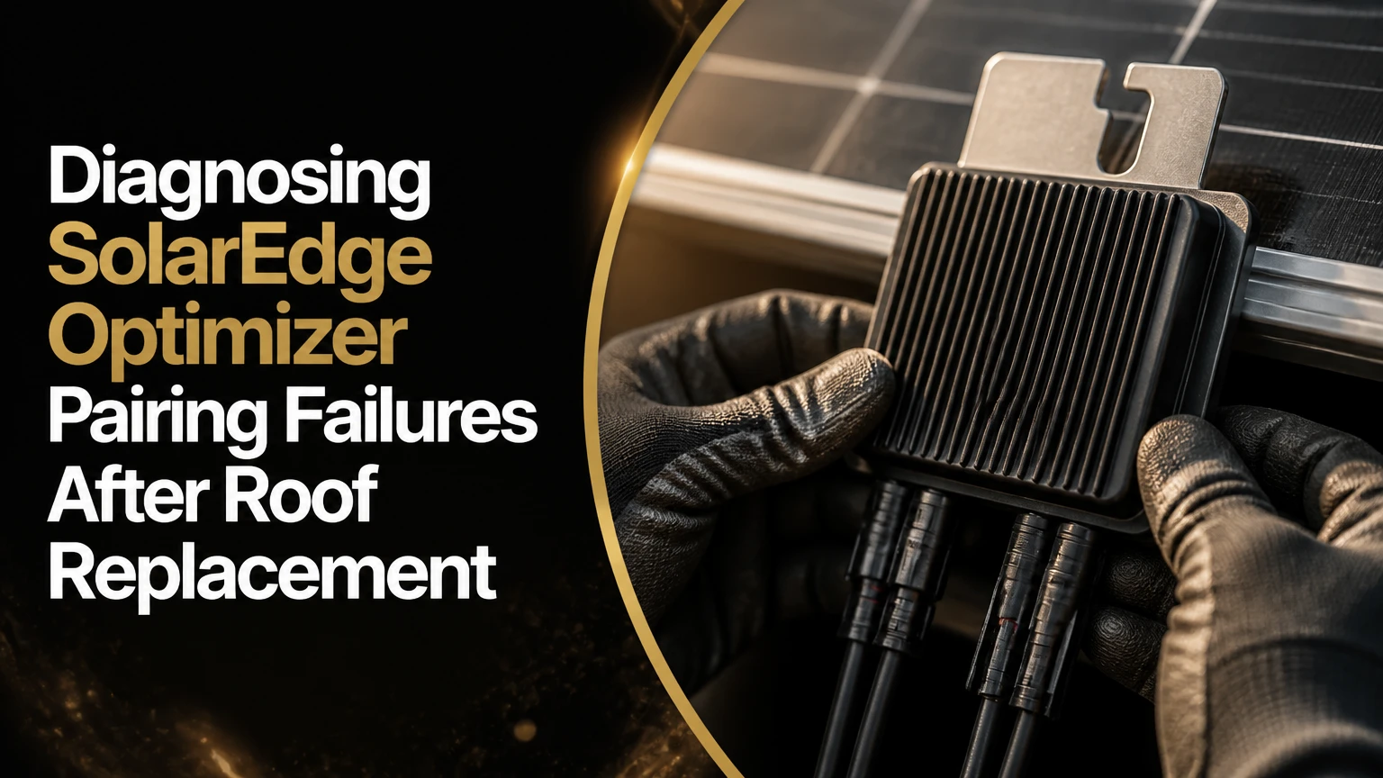
Diagnosing SolarEdge optimizer pairing failures after a roof replacement requires separating communication faults from rewiring, damaged equipment, isolation faults, and incorrect commissioning data. Start with monitoring and inverter status, verify string architecture with a qualified solar technician, then pair once under suitable daylight conditions. Repeated pairing cannot correct an open circuit or incompatible optimizer.
Key Facts
A SolarEdge optimizer normally contributes approximately 1 V in its safety-output state, but the exact diagnostic procedure depends on the inverter and optimizer model.
A roof replacement can create pairing failures when DC connectors, string paths, optimizer serial numbers, or the physical layout no longer match the commissioned system.
An unexpected optimizer count indicates a communication, wiring, compatibility, or registration problem, not automatically a failed optimizer.
SolarEdge pairing must be performed with the correct AC and DC operating sequence for the specific inverter installation guide.
The minimum number of optimizers per string is model-dependent; eight is not a universal rule for every SolarEdge system.
Roof-level DC testing, connector separation, insulation testing, and optimizer replacement require qualified personnel and appropriate photovoltaic safety equipment.
Why Do SolarEdge Pairing Failures Appear After Roof Work?
SolarEdge optimizer pairing failures commonly appear after roof replacements because the array has been electrically interrupted and physically reassembled. The most frequent causes are an unplugged string connector, a reversed or mismatched homerun, a damaged cable, an optimizer replacement that was never commissioned, or a physical layout that no longer matches the monitoring portal.
A roof replacement creates several opportunities for faults that were absent before removal:
- Modules may be reinstalled in a different order.
- DC extension cables may be routed under rails or across sharp edges.
- MC4-compatible connectors may be mixed despite having different manufacturers.
- String jumpers may be left disconnected at a transition point.
- A failed optimizer may be replaced with an incompatible model.
- The installer may restore production without completing the logical layout.
SolarEdge systems use power optimizers as identifiable communication nodes. The inverter must receive power-line communication through the DC circuit and associate optimizer serial numbers with the commissioned system. A physical roof layout change does not always stop production, but it can make panel-level locations inaccurate and complicate fault tracing.
The practical implication is important: pairing failure after roofing is usually an installation or commissioning event before it is an inverter failure. SolarEdge’s remote troubleshooting guidance directs technicians to review inverter status, optimizer communication, string behavior, and event data before replacing equipment.
How Does SolarEdge Optimizer Pairing Work?
SolarEdge pairing links optimizer serial numbers to the inverter so the system can control and report each optimizer. During normal startup, the inverter communicates over the DC conductors, recognizes available optimizers, and builds an operating and monitoring relationship with those devices.
SafeDC changes the voltage behavior of a SolarEdge array when optimizers are not operating normally. SolarEdge documentation describes the safety state as approximately 1 V per optimizer, subject to the product and operating conditions. A string containing 18 optimizers may therefore show a reading near 18 V in a valid safety-output test, but that result alone does not prove every connector, optimizer, and string path is healthy.
The 1 V calculation has limits:
- The number of physical optimizers must be known.
- The modules must receive enough irradiance to activate the optimizers.
- The measurement must follow the applicable SolarEdge test procedure.
- The inverter, disconnects, connectors, and meter must be configured correctly.
- A string may produce an unexpected value if one or more optimizers are inactive, isolated, disconnected, or exposed to a fault.
SolarEdge’s technical safety procedure states, “Each power optimizer will output 1V when not connected to an inverter,” which explains why technicians use the approximate optimizer-count voltage as a diagnostic clue rather than treating it as a complete commissioning test.
What Does the P_OK Count Mean?
The P_OK count is the inverter’s count of optimizers communicating successfully. A lower P_OK count than the installed optimizer count indicates partial communication, while zero P_OK can indicate a disconnected DC path, insufficient operating conditions, incorrect startup state, or a broader inverter fault.
Monitoring data should be interpreted with the installation record, not in isolation. A panel marked N/A may represent an unassociated serial number, a missing communication link, a wrong physical layout, or a device that has not produced recent data. A gray module in the portal is not proof that the module itself has failed.
What Should You Check Before Touching the Array?
Before electrical testing, record the system condition and preserve evidence. Download monitoring events, photograph the inverter display, record the P_OK count, and obtain the roof contractor’s reinstallation photographs, string labels, and optimizer serial-number list.
Before You Start
| Item | Typical value | Why it matters |
|---|---|---|
| Remote review time | 15-30 minutes | Identifies fault timing and affected devices |
| On-site diagnostic time | 1-3 hours | Covers inverter, transition points, and accessible roof wiring |
| Qualified service rate | $150-$250 per hour | Typical out-of-warranty solar labor |
| Pairing wait period | 3-15 minutes | Allows discovery and telemetry population |
| Required records | 4 items | Layout, serials, string labels, and prior production |
| Weather condition | Dry daylight | Reduces false negatives and moisture-related risk |
Do not open inverter covers, separate DC connectors, or climb onto the roof based only on a monitoring alert. Photovoltaic strings can remain energized in sunlight, and SafeDC does not make every exposed conductor harmless during every service condition. SolarEdge installation manuals specify product-specific shutdown and verification procedures.
Step-by-Step Diagnostic Process
A controlled diagnosis normally takes 30 minutes remotely and 1-3 hours on site, depending on array size and roof access. The factor that most determines success is whether the technician verifies the physical DC path before attempting another pairing cycle.
Step 1: Record the Inverter and Monitoring Status
Open the SolarEdge Monitoring Platform or connect with SetApp, if the system supports local commissioning access. Record the inverter model, firmware information, visible error codes, P_OK count, optimizer count, and the time the fault began.
Compare the current system with the pre-roof-replacement record:
- Total module and optimizer count
- Number of strings
- Optimizer model numbers
- Inverter model
- Physical layout
- Production before and after reinstallation
- Any optimizer listed as unassociated
Success checkpoint: The technician can identify whether the failure affects the entire array, one string, or individual optimizers.
Common mistake: Treating a layout mismatch as a communication failure. A system can communicate while reporting devices under incorrect panel positions.
Step 2: Confirm Model and String Compatibility
Check the inverter installation guide and optimizer datasheet for the exact combination installed. Verify the optimizer model, module electrical characteristics, inverter phase type, string limits, and permitted optimizer quantity.
The “eight optimizers minimum” claim is not universal. SolarEdge string minimums vary by inverter family, phase configuration, optimizer generation, region, and design constraints. For example, a short string that worked with one inverter generation may violate the design range of another system.
| Verification point | Required evidence | Failure indication | Correct action |
|---|---|---|---|
| Optimizer model | Part number on device or record | Model absent from compatibility list | Confirm replacement model |
| Module rating | Voc, Isc, power, voltage | Module exceeds optimizer limits | Re-engineer or replace |
| String quantity | Design record and inverter guide | Quantity below or above model range | Reconfigure string |
| String polarity | Labeled positive and negative conductors | Negative meter reading | Stop and trace conductors |
| Serial association | SetApp or monitoring list | Unassociated optimizer | Commission and map device |
Success checkpoint: Every optimizer model and string arrangement is valid for that inverter.
Common mistake: Replacing a damaged optimizer with a visually similar unit. SolarEdge optimizer generations can differ in electrical limits and compatibility.
Step 3: Inspect Ground-Level Connections and Disconnects
A qualified technician should verify that the AC breaker, DC switch, string connectors, and transition equipment are in the expected operating state. The technician should follow the inverter’s shutdown sequence, allow the specified discharge period, and verify voltage before handling conductors.
At ground level, inspect for:
- A DC disconnect left off
- A loose inverter homerun connector
- A string label attached to the wrong input
- Water inside an accessible junction or transition box
- Damaged conduit or pulled cable
- A connector that is not fully latched
Success checkpoint: Each inverter input has the intended string, polarity, and secure connection.
Common mistake: Cycling AC and DC switches repeatedly without recording the sequence. Repeated resets can erase the diagnostic pattern without repairing the physical defect.
Step 4: Measure String Voltage Safely
String voltage testing should be performed only by a qualified photovoltaic technician using a properly rated meter and the SolarEdge procedure for that model. The technician measures the appropriate conductors after isolating the string according to the manufacturer’s instructions.
Approximate readings can guide the next test:
| Observed reading | Likely condition | What it does not prove | Next diagnostic |
|---|---|---|---|
| Near 1 V per optimizer | Optimizers are in safety output | Complete communication is unproven | Pair once after wiring checks |
| Near 0 V | Open circuit, switch issue, or severe fault | Exact break location | Trace string continuity |
| About half expected value | Split string or missing section | Which connector is open | Check junctions and string paths |
| Negative voltage | Reversed polarity | Whether damage occurred | Stop and correct polarity |
| Strongly unstable value | Moisture, isolation fault, or intermittent connector | Dry-weather condition | Insulation and connector testing |
A reading near the expected optimizer count is useful, but it is not the same as a conventional module open-circuit voltage test. SolarEdge optimizers alter string behavior, and the correct interpretation depends on whether the inverter is connected, whether the devices are awake, and how the test is configured. SolarEdge’s safety-voltage technical note should control the procedure.
Success checkpoint: The measured value, polarity, string identity, and test conditions are documented for every string.
Common mistake: Applying the simple formula “one volt equals one panel” as definitive proof that every optimizer is connected. The formula is a screening clue, not a full fault-isolation method.
Step 5: Inspect the Roof Wiring and Connectors
If the voltage or polarity is abnormal, inspect the roof-level string path. The technician should compare the actual wiring with the pre-removal photographs and the current layout, then trace each optimizer output through the string.
Post-roof-replacement defects commonly include a connector from one optimizer plugged into the wrong lead, a disconnected jumper, a cable pinched under flashing, and a connector resting where water collects. A connector that appears joined may still have a poor crimp, incompatible housing, damaged seal, or incomplete latch.
MC4 connectors require particular care. “MC4-compatible” does not guarantee that two connector brands are approved for mating. The National Electrical Code and manufacturer instructions require listed, compatible equipment and suitable installation practices; the precise requirements depend on the jurisdiction and edition adopted locally.
Success checkpoint: The string follows one continuous, documented path, with connector pairs matched to the approved components.
Common mistake: Pulling or twisting connectors under load. The circuit must be isolated and verified by a qualified person before separation.
Step 6: Test Isolation and Arc-Fault Conditions
Isolation faults and arc-fault alerts are different from ordinary pairing failures. An isolation fault indicates unwanted current leakage between the DC circuit and ground, while an arc-fault alert may result from damaged conductors, loose connections, or connector problems.
| Fault category | Typical evidence | Common post-roof cause | Professional test |
|---|---|---|---|
| Communication loss | Low P_OK or N/A devices | Open connector or wrong string path | String tracing and pairing logs |
| Isolation fault | 03x9a or related event | Pinched insulation or wet connector | Insulation resistance testing |
| Arc fault | Arc-fault event or shutdown | Loose or damaged connection | Connector and conductor inspection |
| Layout mismatch | Correct count, wrong positions | Modules moved during reinstall | Serial-number and map comparison |
| Hardware failure | One optimizer remains absent | Mechanical or electrical damage | Manufacturer-approved optimizer test |
Error-code interpretation varies by inverter firmware and product family. Use the exact code definition in the SolarEdge manual or installer support record rather than relying on a generic internet code list.
A megohmmeter test may help locate insulation damage, but test voltage and disconnection requirements must follow SolarEdge instructions. Applying an inappropriate test voltage to connected electronics can damage equipment or invalidate the result.
Why Is Only One Panel or One String Missing?
A partial pairing failure usually points to a localized wiring or device problem rather than a failed central inverter. When most optimizers appear and one section does not, the likely search area is the boundary between the last communicating optimizer and the first missing device.
A technician should compare the missing devices with physical string boundaries. If all missing panels occupy one roof section, inspect the section’s homerun, transition connector, and first or last optimizer. If missing panels are scattered across several strings, investigate serial association, layout records, optimizer compatibility, or a shared commissioning error.
A single replacement optimizer can also create a panel-level N/A status. The replacement may be electrically functional but absent from the inverter’s commissioned device list. The remedy is to verify the serial number, add or associate it through the approved commissioning workflow, and update the physical layout.
When Should You Run Pairing Again?
Run pairing only after the physical string paths, polarity, compatibility, and safety condition have been checked. Pairing is a commissioning operation, not a substitute for repairing an open circuit, isolation fault, incompatible optimizer, or disconnected homerun.
Use the approved SetApp workflow for the inverter. Some models also permit pairing through the inverter’s P position or physical switch, but the timing and startup sequence vary. A typical process is:
- Restore the verified AC and DC configuration according to the manual.
- Confirm the inverter indicates the correct operating state.
- Start pairing through SetApp or the approved inverter control.
- Wait through the complete discovery period.
- Review the final P_OK count and optimizer event log.
- Confirm that production and device telemetry remain stable.
The initial countdown may finish in several minutes, while a complete optimizer list can take longer to populate. Allow up to 15 minutes when the manufacturer procedure or installer workflow specifies that period.
Success checkpoint: The final communicating optimizer count equals the documented installed count, and no unresolved isolation or arc-fault event remains.
Common mistake: Starting five consecutive pairing cycles because one device did not appear immediately. Repetition can obscure whether the problem is electrical, environmental, or administrative.
Which Repair Path Is Best?
The best repair path is a qualified SolarEdge technician when roof-level wiring, DC connectors, optimizer replacement, or isolation testing is involved. The roofing contractor should be notified immediately and given a documented opportunity to correct workmanship defects, but a roofer without photovoltaic qualifications should not perform live DC diagnostics.
| Repair option | Typical cost | Typical time | Best use | Main limitation |
|---|---|---|---|---|
| Roofer inspection | $0 under workmanship claim | 1-5 business days | Visible cable or mounting damage | May lack SolarEdge access |
| Independent solar technician | $300-$750 typical visit | 1-3 hours on site | Wiring and pairing diagnosis | Upfront payment |
| Manufacturer-supported installer | $150-$250 per hour typical | 2-10 business days | Complex commissioning or warranty case | Scheduling delay |
| DIY monitoring review | $0 | 15-30 minutes | P_OK and event recording | Cannot safely prove roof wiring |
| Optimizer replacement | $85-$140 part range, if out of warranty | 1-3 hours with access | Confirmed failed device | Labor and compatibility still apply |
SolarEdge power optimizers commonly carry long limited warranties, but warranty eligibility depends on the product, purchase date, installation conditions, and cause of failure. Mechanical damage caused during roofing may become a workmanship claim rather than a manufacturer claim. Obtain the warranty decision in writing.
What Evidence Should the Homeowner Request?
A homeowner should request a string verification record, optimizer serial-number list, commissioning result, and photographs before accepting the roof-related solar work. Those records establish whether the array was electrically restored and whether a later failure originated during removal or reinstallation.
The acceptance packet should include:
- Date and weather conditions during testing
- Inverter model and firmware
- Optimizer model and serial numbers
- Physical layout with panel positions
- String count and homerun labels
- Measured polarity and voltage
- Final P_OK count
- Isolation and arc-fault status
- Monitoring screenshot after stable production
- Names and qualifications of the people who performed electrical work
This documentation also prevents a common dispute. A contractor may state that the system “turns on,” while the homeowner needs proof that every optimizer communicates and that the monitoring map remains accurate.
What Are the Most Common Diagnostic Mistakes?
The most damaging mistakes are interpreting one voltage number as a complete diagnosis, pairing before repairing the string, and replacing optimizers without checking compatibility or serial association.
Mistake 1: Assuming Eight Optimizers Always Meet the Minimum
String requirements vary by inverter and optimizer model. Use the exact SolarEdge design rules, not a generic minimum copied from another residential system.
Mistake 2: Blaming the Inverter First
A central inverter can report widespread pairing loss because one homerun is open or incorrectly connected. Verify the DC path before recommending inverter replacement.
Mistake 3: Ignoring Weather Dependence
Moisture can trigger intermittent isolation faults that disappear during a dry inspection. Record whether the fault occurs after rain, overnight condensation, or heavy washing.
Mistake 4: Treating the Monitoring Layout as Electrical Wiring
The logical panel map identifies devices for reporting. Editing the map cannot repair a reversed string, disconnected optimizer, or damaged conductor.
Mistake 5: Using Unapproved Connector Combinations
Connector housings can mate mechanically while failing sealing, contact, or listing requirements. Replace questionable pairs with approved, compatible components.
Expert Practitioner Rules
- Trace from the inverter toward the last known communicating optimizer when only one roof section is missing.
- Compare the fault start time with the roofing completion date before replacing hardware.
- If the P_OK count is correct but panel positions are wrong, repair the digital layout first, not the DC wiring.
- A stable result after one dry-day pairing does not clear an insulation defect that appears only when wet.
How Much Does SolarEdge Pairing Repair Cost?
A typical post-roof-replacement diagnosis costs $300-$750 for an independent solar service visit, while a confirmed optimizer replacement may add an $85-$140 component cost plus labor. A simple connector correction can take under two hours, but concealed cable damage, difficult roof access, warranty authorization, and permit requirements can extend the job from several days to multiple weeks.
| Scenario | Typical labor | Parts or fees | Likely duration |
|---|---|---|---|
| Incorrect switch or ground-level connection | $150-$300 | $0-$50 | Same day |
| One loose or damaged connector | $300-$750 | $20-$100 | 1-3 hours |
| One optimizer replacement | $300-$750 | $85-$140 | 1-3 hours |
| Insulation fault under roofing | $450-$1,200 | $50-$300 | 1-2 visits |
| Warranty replacement | $300-$750 labor | Potentially $0 part cost | 1-3 weeks |
| Full re-commissioning and remapping | $450-$1,000 | Usually no major parts | 1-2 business days |
These are typical service ranges, not guaranteed prices. Roof pitch, travel distance, local licensing requirements, equipment age, and responsibility for the defect can materially change the invoice.
When Is Pairing Not the Real Repair?
Pairing is not the real repair when the system has an active isolation fault, arc-fault condition, damaged conductor, incompatible optimizer, failed inverter communication board, or undersized or improperly designed string. Pairing can complete while an intermittent physical defect remains, creating a repeat failure days later.
A technician should escalate beyond pairing when:
- The same optimizer repeatedly disappears.
- Voltage changes substantially between dry and wet conditions.
- An isolation fault returns after reset.
- The optimizer count is correct but production remains zero.
- The inverter cannot enter a stable operating state.
- The replacement optimizer is unsupported or electrically mismatched.
- The inverter displays a hardware or communication-board fault.
SolarEdge support may request event logs, firmware details, serial numbers, and test results before authorizing equipment replacement. Providing those records is faster than reporting only that “the panels are not pairing.”
FAQ
Can a roof replacement damage SolarEdge optimizers?
Yes. Optimizers can suffer connector, cable, enclosure, mounting, or water-ingress damage during removal and reinstallation. A missing optimizer count does not prove physical damage, however, because an unplugged string or unassociated replacement can produce the same monitoring symptom.
Can pairing work on an overcast day?
Pairing may work in overcast daylight if the modules provide adequate operating energy, but weak irradiance can produce unreliable or incomplete discovery. A qualified technician should repeat the manufacturer-approved process in stable daylight after correcting physical and compatibility issues.
Does changing the panel order break SolarEdge pairing?
Changing panel order does not necessarily prevent electrical pairing, but it can make the monitoring layout inaccurate. The installer should update the physical layout with the correct optimizer serial number at each panel position after the array is reinstalled.
Should I pay the roofer before the system is repaired?
Withholding payment can create contractual or legal complications, so review the roofing agreement and local law before taking action. Promptly provide written notice, photographs, monitoring records, and a qualified technician’s findings, then request correction under the workmanship terms.
Can I test SolarEdge optimizer voltage myself?
A homeowner can review monitoring data and record inverter status, but roof-level DC testing and connector work should be performed by a qualified photovoltaic technician. Daylight strings can remain energized, and an incorrectly rated meter or unsafe disconnection can cause serious injury.
How long should SolarEdge pairing take?
The visible pairing countdown may finish in roughly 3-5 minutes, while complete optimizer discovery and telemetry can require up to 15 minutes under the applicable commissioning procedure. Confirm the final optimizer count after the waiting period rather than judging success from the initial screen.
The Bottom Line
Diagnosing SolarEdge optimizer pairing failures after a roof replacement starts with evidence, not repeated resets. Record P_OK counts and event codes, verify the exact optimizer and inverter compatibility, test string polarity and voltage through a qualified technician, inspect post-roof wiring, and run pairing only after the physical circuit is sound. The final acceptance standard is a complete optimizer count, stable production, accurate panel mapping, and no unresolved safety fault.